Sequential Turning | |||||
|
| ||||
Strategy Parameters
 Properties
- Edit the selected motion.
 Delete
- Delete the selected motion.
 and
and 
- Change the rank of the selected motion.
 Go
Go- In Go motion, the program positions the tool with respect to one or two
check elements.
- Geometry tab
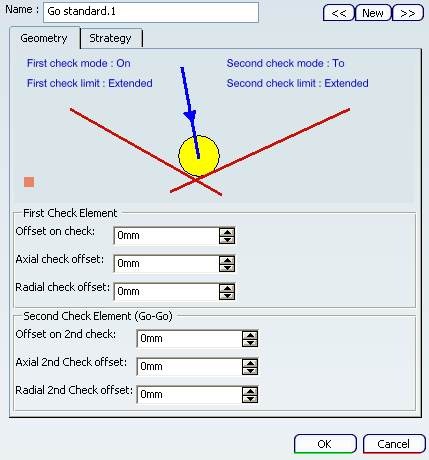
- First/Second Check Modes
- The tool is positioned with respect to each check element depending on
the To, On, and Past mode:
- To: The tool nose is positioned tangent to the near side of the selected element with a possible offset.
- On: The tool nose is positioned on the selected element, with a possible axial or radial offset (normal offset, collision avoidance and safety angles are not applicable).
- Past: The tool nose is positioned tangent to the far side of the selected element with a possible offset.
- Check Element
- The first check element can be point, line, curve, or edge type elements. If it is a point, no second check element can be selected. Otherwise, the second check element can be line, curve or edge type elements. When only one check element is selected, the tool is projected onto the check element. When two check elements are selected, the tool is positioned with respect to the two check elements.
- First/Second Check Limit
- Extended: When check limit mode is set to Extended, a virtual tangent element is added to each extremity of the check element before it is actually taken into account as a check element. Therefore, if there is no intersection between the drive and check elements, the final tool position may be located at the intersection of the drive curve and a tangent of the check element.
- Actual: When check limit mode is set to Actual, no virtual tangent element is added. Therefore, the final tool position is located on the check element.
Furthermore, control over geometric extrapolation is not controlled in the Follow motion but on the preceding motion that positions the tool on the drive element. Collision avoidance is taken into account for positioning in On mode, and that left and right safety angles are only considered in collision avoidance mode.
- Reference Point
- For the first Go motion of an operation, you can define
a chosen direction of motion by means of a reference point. This reference
point can be used in determining the exact tool position considering the
check modes, offsets, and so on.
Reference Point in the First Go Motion of the Operation: The tool positioning for the first motion of a Sequential Turning operation with respect to To, On, and Past mode is specified according to a reference point. This point can be derived from the previous operation or can be selected using the Reference Point symbol in the dialog box.
Reference point definition is optional. If a reference point is not defined, the tool is positioned by default with respect to the check elements depending on the To, On, and Past mode setting.
Click point symbol
 in the Geometry tab of the dialog box and then select
the desired point or right-click the symbol to display the following contextual commands.
in the Geometry tab of the dialog box and then select
the desired point or right-click the symbol to display the following contextual commands.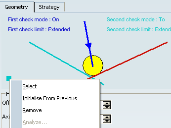
- Select: Pick a point as a reference from the authoring window.
- Initialise from Previous: Automatically take a reference point which has been initialised from the previous machining operation or tool change. If the current Sequential Turning Operation immediately follows a tool change, then Initialise from Previous takes the tool change point as reference point. Otherwise it can be the last point of the previous Machining Operation (which is the end point of the retract motion, if a retract motion is present on the previous Machining Operation).
- Analyze: Visualise the reference point in the authoring window.
- Remove: Reject the previous selection and make a new selection.
To illustrate reference point behavior, the figures below have identical check modes on both check elements. The only difference is the position of the reference point. Notice how a change in reference point affects the tool position.

With a new reference point position:

- Offsets
- Specifies axial, radial, and normal offsets with respect to each check element.
Note:
The positioning mode (To, On, Past) and offsets are not applicable when the tool is positioned on a point.
- Strategy tab
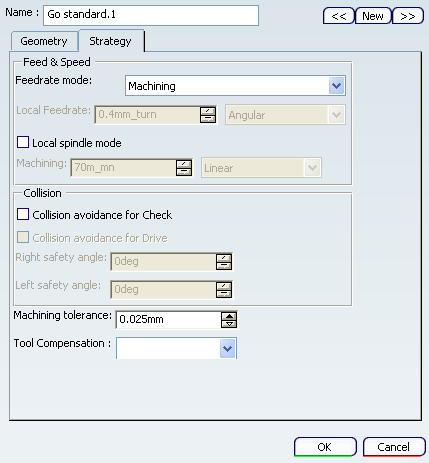
- Feedrate mode
- Specifies feedrate mode as:
- Machining
- Lead-In
- Lift-Off
- RAPID
- Other value
- Air cutting feedrate
- Local Feedrate
- Specifies local feedrate only when feedrate mode is Other value.
- Local spindle mode
- Specifies spindle speed.
- Collision avoidance for Check/Drive
- Collision avoidance for each check element when the tool is positioned in To or Past mode.
- Left and right safety angles
- Specifies left and right safety angles.
Available when Collision avoidance for Check check box is selected.
- Machining tolerance
- Specifies machining tolerance.
- Tool compensation
- Specifies tool compensation.
- Geometry tab
 Go Delta
- In Go Delta motion, the tool move is based on the current position of
the tool. The To, On, and Past mode is not proposed.
- Geometry tab
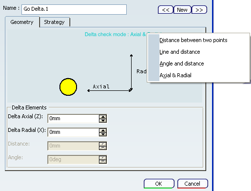
- Delta check mode
- The following options are available
- Distance between two points: Select two points in the authoring window.
- Line and distance: Select line and distance in the authoring window.
- Angle and distance: Select angle and distance in the authoring window.
- Axial and radial: Select axial and radial offsets in the authoring window.
- Strategy tab
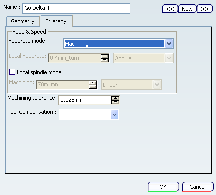
The following options are available:
- Feedrate and spindle speed
- Machining tolerance
- Tool compensation
- Geometry tab
 Go InDirv
- In Go InDirv(Go in Direction Vector) motion, the tool moves in a given
direction up to the selected check curve.
The tool is positioned with respect to the selected element depending on
the To, On, and Past mode.
- Geometry tab
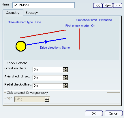
- Check Mode
- Specifies check mode as:
- To: The tool nose is positioned tangent to the near side of the selected element with a possible offset.
- On: The tool nose is positioned on the selected element, with a possible axial or radial offset (normal offset, collision avoidance and safety angles are not applicable).
- Past: The tool nose is positioned tangent to the far side of the selected element with a possible offset.
- Drive Element Type
- Specifies drive element type as Line or Angle. Also specifies Angle of drive, if drive element type is Angle.
- Drive Direction
- Specifies drive direction as Same or Inverted.
- Check Limit
- Specifies check limit as Extended or Actual.
- Offset
- Specifies axial, radial, and normal offsets with respect to the check element.
- Strategy tab: The following options are available:
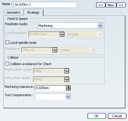
- Feedrate and spindle speed
- Collision avoidance when the tool is positioned in To or Past mode.
- Left and right safety angles: Available when Collision avoidance for Check check box is selected.
- Machining tolerance
- Tool compensation
- Guiding Point, if a square or grooving insert is used.
- Geometry tab
 Follow
- In Follow motion, the tool follows a drive element up to a check element.
The check element is to be selected in the Follow motion and can be an edge,
line, a curve, or a point.
- Geometry tab:
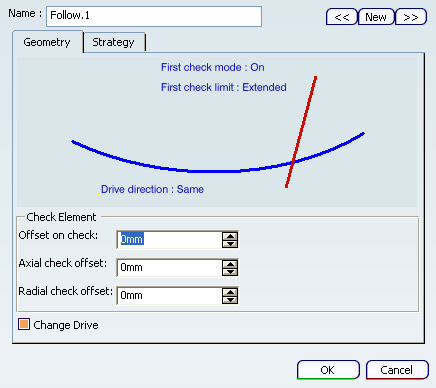
The drive element is a curve on which the tool is positioned by a preceding motion. Therefore, the preceding motion must be a Go, Go InDirv, or Follow motion. A Go to a point or a Go Delta cannot precede a Follow motion.
- Drive direction
- Specifies Same or Inverted.
This is useful in the particular case when two positions are reachable.
- Offset
- Specifies axial, radial and normal offsets with respect to the check element.
- Control over Geometric Extrapolation of Check Limit
If the preceding motion is a Go motion, the first selected check curve is used as drive curve for the Follow motion.
If the preceding motion is a Go InDirv motion, the selected check curve is used as drive curve for the Follow motion.
If the preceding motion is a Follow motion, the check element of the preceding Follow motion is used as drive curve when this check element is not a point and the Change Drive option of the preceding Follow motion is set. Otherwise, both consecutive Follow motions share the same drive curve.
Note:
- the offsets applied to follow the drive element are also defined on the same preceding motion. When the drive and check curves are tangent, any offset values on the check curve should be the same on the tangent drive curve.
- the collision avoidance and the control over geometry extrapolation on drive curve are also defined on the same preceding motion.
- Check mode
The tool follows the drive element up to the check element. The final tool position is determined by the To, On, and Past mode.
- To: Tool nose tangent to the drive element and before the check element with a possible offset.
- On: Tool nose tangent to the drive element and on the check element, with a possible axial or radial offset (normal offset is not applicable).
- Past: Tool nose tangent to the drive element and after the check element with a possible offset.
- Strategy tab: The following options are available:
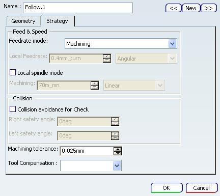
- Feedrate and spindle speed
- Collision avoidance for Check.
- Left and right safety angles: Available when Collision avoidance for Check check box is selected.
- Machining tolerance
- Tool compensation
- Guiding Point, if a square or grooving insert is used.
- Geometry tab:
 PP Word
- Inserts a tool motion defined by PP word statements (access to a PP word table is available if one is defined on the machine of Part Operation).


![]()
Geometry Selection for Sequential Turning
You can select lines, curves, and edge elements as check and drive elements. Points can also be selected as checks. Selected elements must be located in the plane defined by the machine spindle axis and radial axis.
The following cases summarizes how the tool is positioned with respect to a check element depending on the To/Past modes and negative/positive offset values.
Case 1: Check Mode: To and Positive offset
Case 2: Check Mode: To and Negative offset
Case 3: Check Mode: Past and Positive offset
Case 4: Check Mode: Past and Negative offset
![]()
Tools
All tool types with compatible inserts are authorized. The internal  and external
  threading insert-holders with thread
  inserts may be used.
If there are no previously created tool motions listed in the Sequential Turning dialog box, the first one must be a Go Standard motion to a point. It specifies either the absolute start position from where the following position can be computed or the end point of the approach macro (if the operation has one).
See Specifying a Tool Element in a Machining Operation and Creating or Editing a Probing, a Milling, or a Drilling Tool.
![]()
Feedrates and Spindle Speed Parameters
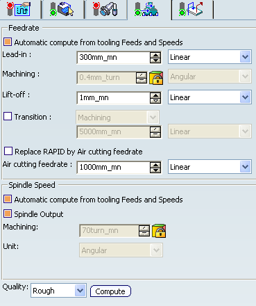
- Feedrate: Automatic compute from tooling Feeds and Speeds
- This check box allow a Machining Operation feeds and speeds values to be updated automatically when the tool's feeds and speeds value are modified.
You can specify the following feedrates:
- Lead-in: Applied during the lead-in and attack distance.
- Machining
- Lift-off
- Transition
- You can locally set the feedrate for a transition path to a
Machining Operation B from a Machining Operation A or from a tool
change activity. This is done by selecting the Transition check box in the Machining Operation dialog box for
operation B.
See the Setting a Transition Feedrate.
- Replace RAPID by Air cutting feedrate
- Select this check box to replace RAPID feedrate in tool trajectories (except
in macros) by Air cutting feedrate.
The changes in unit of Air cutting feed-rate, are also reflected in APT file output. Calculated cycle time in Properties dialog box of Machining Operation also get changed. There are changes in total time and machining time on Tool Path Replay dialog box.
Note:
The feedrates and Air cutting feedrate can be defined in linear (feed per minute) or angular (feed per revolution) units.
- Angular: feedrate in revolutions per minute and unit is set to mm_turn.
- Linear: feedrate in feed per minute and unit is set to mm_mn.
- Spindle Speed: Automatic compute from tooling Feeds and Speeds
This check box allow a Machining Operation feeds and speeds values to be updated automatically when the tool's feeds and speeds values are modified.
If the Feedrate Automatic compute check box is selected and the Spindle Speed: Automatic compute from tooling Feeds and Speeds check box is not selected, then only the feedrate values can be computed. If both are not selected then automatic updating is not done.
When you modify a tool's feeds and speeds, all existing Machining Operation with the Automatic compute check boxes selected that use this tool (or an assembly using this tool) can be recomputed.
- Spindle output
- This check box manage output
of the SPINDL instruction in the generated NC data file. The instruction is generated, if the check box is selected. Otherwise,
it is not generated
Note:
The spindle speed can be defined in linear (length per minute) or angular (length per revolution) units.
- Angular: length in revolutions per minute and unit is set to mm_turn.
- Linear: length in feed per minute and unit is set to mm_mn.
- Quality
- The feed and speed values are computed according to the Quality setting on the Machining Operation.
- Compute
- Feeds and speeds of the Machining Operation can be updated according to tooling feeds and speeds by clicking the Compute button.
Feeds and speeds of the Machining Operation can be updated automatically according to tooling data and the rough or finish quality of the Machining Operation. See About Feeds and Speeds.
![]()
Macro Parameters
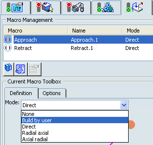
The selected macro type (Approach or Retract) defines the tool motion before
or after machining:
- Approach: to approach the Machining Operation start point.
- Retract: to retract from the Machining Operation end point.
The proposed macro mode are:
- None
- Build by user
- Direct
- Radial-axial
- Axial-radial
Various feedrates are available for the approach and retract motions (RAPID, lead-in, lift-off, and so on). Local feedrates can be set to either Angular units (length per revolution) or Linear units (length per minute). See Defining Macros