Creating a Sequential Turning Operation | ||||
|
| |||
Activate the Manufacturing Program and click Sequential Turning
 in the Lathe Machining Operations toolbar.
 A Sequential Turning entity is added to the Manufacturing Program. The Sequential Turning operation dialog box appears with the Geometry tab
 .
.Select the Strategy tab
 .
.
Still in the Strategy tab
.- Select Go
 and define the first motion parameters.
Note: The first motion must be a Go motion to a point.
- Select Go
again to define the second
motion parameters.
- Set the first and second Check Modes to To.
- Click OK to define the motion.
- Select Go
again to define the next motion.
- Select Go InDirv
 .
. - Click OK to define the motion.
- Select Follow
 .
.The check curve of the previous motion is used as drive curve. This drive element is highlighted in the 3D view
- Click OK to define the motion.
- Select PP Word
 ,
then specify a PP word (DELAY/5, for
example) in the dialog box that appears.
,
then specify a PP word (DELAY/5, for
example) in the dialog box that appears. - Select Go Delta

- Click OK to define the motion.
The defined motions are shown below.
- Select Go
Right-click any motion to access the contextual menu.
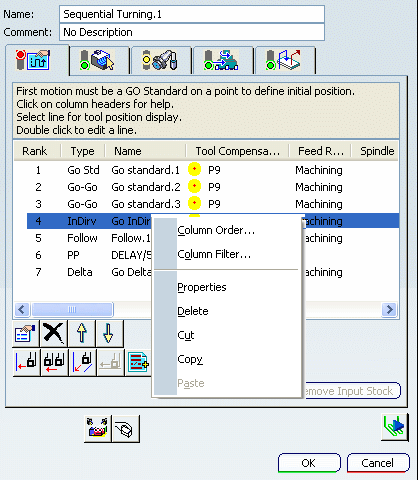
- Column Order: Allows to change the header column order with Up and Down buttons.
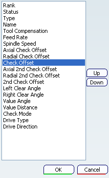
- Column Filter: Allows to filter the header columns.
- Properties: Allows to modify the selected motion.
- Delete: Removes the selected motion.
- Cut: Cut the selected motion.
- Copy: Copy the selected motion.
- Column Order: Allows to change the header column order with Up and Down buttons.
Go to the Tool tab
 to select a tool.
 Select the Feeds and Speeds tab
 to specify the feedrates and spindle speeds for the Machining Operation.
Select the Macros tab
 to specify the operation's transition paths.
See Define Macros on a Lathe Operation for more information.
Click Tool Path Replay
 to check the validity of the Machining Operation.
- The tool path is computed.
- A progress indicator is displayed.
- You can cancel the tool path computation at any moment before 100% completion.