Create an Empty
Projection View in an Existing Layout
You can create an empty projection view in an existing layout.
Click New View
 in the Layout toolbar.
The preview of the 2D view frame along with the robot is
displayed in the sheet. Depending on a possible selection, the robot lets
you change either the primary view type (no selection), or the view box orientation.
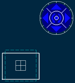
You can redefine the projection plane using the blue arrows
of the robot at any time before the view creation: to the bottom, the left,
the right, the top, or rotated using the given snapping or according to an
edited rotation angle. For more information, refer to
Define the View Orientation During View Creation.
You can change the view position by dragging the dotted frame
or pressing the Ctrl key and moving the cursor to the desired
location.
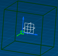
The preview of the view box is displayed in the 3D window:
Notes:
Click on the sheet to position the new view.
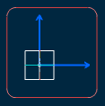
An empty primary view is created, displaying a blue axis in a red frame. Additionally, the FRONT node is added to the specification tree.
You can now create 2D geometry in your view or continue creating
more projection views as detailed below. Click New View  again and click in the layout at the location where you want the projection
view to be positioned: you can create left, right, top, bottom and isometric
views. Create a LEFT view, for example.
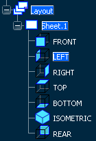
The view is created. The specification tree is updated again
to show the newly created view.
Double-click the New View icon to create several
projection views one after the other: this time, create RIGHT, TOP, BOTTOM
and ISOMETRIC views. The specification tree is updated again. Press Esc when you have created your views. Double-click one of the projection views to activate it.
For example, activate the LEFT view. Click New View
 again: This time, you can create rear or isometric views from the left view.
Create a rear view, for example.
 The specification tree is updated again.

Define the View Plane and Resize the View Bounding Box During View Creation
You can define or modify the primary view plane and resize the view bounding box when selecting a 3D reference element during view creation. It also allows you to position the center of the view's bounding box on the sheet, rather than the origin of the view.
Select the Change primary view plane and Resize view box according to 3D model check boxes in Tools > Options > 2D Layout for 3D Design > View Creation tab, under the Primary View area. Click New View
 in the Layout toolbar.
 The preview of the 2D view frame along with the robot is
displayed in the sheet and the view bounding box is displayed in the 3D window.
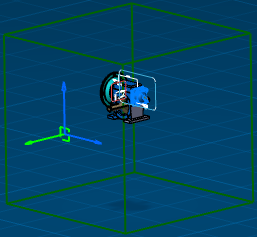
Select a plane to change the primary view plane and resize the view box according to 3D model. Note:
For more information about selecting a reference element, refer to More About Creating a Projection View.
The primary view plane is changed and the view box is resized according to the 3D model.
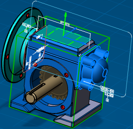
Click on the sheet to position the new view. The view is created and additionally the FRONT node is added in the specification tree.

Define the View Orientation During
View Creation
You can define the orientation in the view while creating it.
Click New View
 in the Layout toolbar and select a face from 3D.
 Click the right or left arrow on the robot to visualize the
left or right side, respectively.
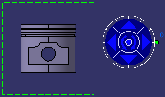
Click the top arrow to visualize the bottom side.
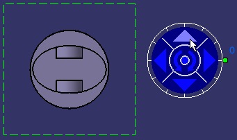
Click the counterclockwise arrow to rotate the reference
plane.
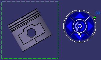
Drag the green knob to redefine the rotating angle. The default
increment value is 30 degrees.
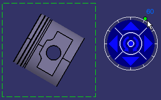
Right-click the knob and select the required option to modify the increment value.
-
Free hand rotation: Lets you rotate the knob
in a free manner using the mouse, instead of snapping it to a given increment.
-
Incremental hand rotation: Snaps the rotation
to a given increment (from 30 to 30 degrees, between zero and 330). This
is the default value.
-
Set increment...: Displays the Increment
Setting dialog box. Enter the required value in the Increment
value field. For example, type 5 deg (for 5 degrees) and click
OK.
-
Set current angle to:
-
0 deg: Sets the current angle value to 0 degree.
-
90 deg: Sets the current angle value to 90
degrees.
-
180 deg: Sets the current angle value to 180
degrees.
-
270 deg: Sets the current angle value to 270
degrees.
-
Set angle value...: Displays the Angle
Setting dialog box. Enter the required value in the current
angle (deg) box.
Click on the center of the robot to set the position of the
view.
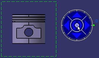
The view is created.
|
![]()


