About View Creation | |||||
|
| ||||
Support of 3D Shapes
Projection views may be defined to fit the layout representation of a 3D shape.
Projection views of the 3D shape are defined in the 2D Layout for 3D Design window:
![]()
Support of Assemblies
Projection views may also be defined to fit the layout representation of an assembly.
Projection views of the layout representation of the assembly and its context are defined in the 2D Layout for 3D Design window:
Important:
Assembly
layouts are taken into account by the following functionality:
|
![]()
View Box
The data needed to fully define the layout of a view set in the 2D window, as well as the position of each view in the 3D space, is defined in the standards, using a "view box".
This data is made up of:
A single, default, view box is defined for each standard (for example, there is a single view box for the ISO_3D standard). The standard definition is retrieved when creating the first view of a view set: the view box definition is associated to each view set. Therefore, an update of the standard does not impact existing views, or views added to an existing view set.
For more information, refer to Layout Views Customization.
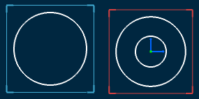
View Box Anchor Point
The view box anchor point is the 3D point from which the view box position in 3D space is defined. It is defined in the standard. Two anchor points are available (the primary view is displayed in red in the images below):
- At the bottom left corner of the view box:
- At the center of the view box:
3D Axis
The view plane definition corresponds to the specific position of design views in the 3D space. It is defined in the standard. In 2D Layout for 3D Design, coordinates are always expressed as local coordinates (H, V). Local coordinates are transformed to be expressed in 3D space using the view plane definition.
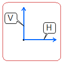
The 3D axis gives the primary view orientation in space. Its first direction corresponds to the view local direction H while its second direction corresponds to the view local direction V. The third direction is deduced from the H and V directions in order to form an axis system.
3D Axis Origin
The 3D axis origin corresponds to the position of the view box's anchor point in 3D space, i.e. its center or bottom left corner.
In the example shown here, the anchor point is placed at the bottom left corner of the view box.
Specifying this position is particularly important when the 3D shape is designed in an assembly (as for a rear bumper). When the 3D shape is designed in order to be multi-instantiated in the assembly, this position is generally null (as for wheels).
The 3D axis orientation of projection views, isometric views, section views, section cuts and auxiliary views depends on the following factors:
- The active view 3D axis orientation.
- The position of the cursor on the layout.
- The projection method.
The 3D axis orientation can be modified by selecting a 3D element when creating a view. This 3D element can belong either to a 3D shape or to an assembly:
- In the case of a standalone 3D shape, the primary view lies on a plane parallel to the selected element as well as on the view box fitting the 3D shape.
- In the case of a 3D shape in the context of an assembly, the primary view lies on a plane parallel to the selected element as well as on the view box fitting the 2DL assembly.
View Box Overall Dimensions
The overall dimensions are as follows:
- The distance between the Front and Rear views.
- The distance between the Right and Left views.
- The distance between the Top and Bottom views.
The view box overall dimensions define approximately the size of the design. They are computed to hold as tightly as possible the 3D shape or assembly. For this reason, the view box may be a cube or a rectangular parallelepiped.
| Important: All elements that cannot be zoomed (i.e. planes, infinite lines) and 3D annotations are not taken into account when computing the view box. If the 3D shape or assembly contains only elements that cannot be zoomed and/or 3D annotations, then all these elements are taken into account to avoid getting a bounding sphere with a size of zero. |
![]()
View Frame
For views located in design sheets, the view frame has rounded corners and it is displayed using a solid linetype. For 2D component reference views (located in detail sheets), the view frame has a solid linetype and strengthened square corners. The following table depicts the type of view frame color each view has:
| View | View frame color |
|---|---|
| Active | Red |
| Projection | Blue |
| Section | Green |
| Section cut | Yellow |
| 2D component | Blue |

![]()
View Set
A view set can be associated to an independent view box. This is what happens when you create a primary view, for example. However, a view set does not have an associative view box when it is initiated from a view from 3D plane creation.
It is not possible to create several projection views of a same type within a set of views (two Right views, for example). If needed, you can either start a new view set (that is create a new primary view) or create an auxiliary view from the related view. However, it is possible to create several isometric views or several section views/cuts.
Existing view sets are not impacted by changing standards as they are linked to independent view boxes, if any. If you need to create views according to a view box different from the one stored in the document's standard, then you first need to switch to a standard containing the new definition, and finally to start a new view set.
Existing view sets can still be extended after a standard update. The definition of new projection views is found from the view box associated to the set of views.
When defining the view box, you can invert the naming of the Left and Right views if you want the Right view to be called Left view, and vice-versa. This only inverts the name (not the type) of the views.
![]()
View Position
Positioning a view during its creation defines the projection view direction, in accordance with the projection method and the primary view type.
For information on the projection method, refer to About the Projection Methods. For information on the primary view type, refer to About 2D Layout For 3D Design Views.
![]()
View Text
The view name and the view scale are displayed in the view as per the settings done by the administrator.
For more information, refer to Managing View Texts.
![]()
Propagation of the Reference View Scale
Primary views are created using the sheet scale. Projection views, sections (including multi-plane section views) and auxiliary views are created using the scale of the reference view.
If you change the sheet scale (defined in the sheet properties), the scale of all existing views (defined in the view properties) is multiplied by that of the sheet (for example, if existing views already have a scale of 1/10, and if you change the sheet scale to 1/10, then existing views will now have a scale of 1/100).