Right-click a solution in the specification tree,
and select Create Sensor.
The Create Sensor dialog box appears. Choose the type of sensor you want to create by
selecting one of the following tab: - Global to create a global sensor. A global sensor is a physical output of a computation for the entire model.
- Local to create a local sensor. A local sensor is a physical output of a computation restricted to a local area.
- Resultant to create a resultant sensor. A resultant sensor is a physical output that represents the resulting force and moment at restraint specifications.
Select one or several sensors in the selected tab. The
list of available sensor depends on the type of solution
(mono-occurrence or multi-occurrence solution). Click OK.
- If you selected a global sensor, the sensor is created and appears in the specification tree under the selected solution.
- If you selected a local sensor, the Local Sensor dialog box appears.
- If you selected a resultant sensor, the Reaction Sensor dialog box appears.
If you selected a local sensor: - Select a support for the local sensor.
You can select geometries, meshes, and groups.
- If the local sensor is created for a multi-occurence solution, all the occurrences are selected by default. To filter and select the occurrences you want to use, select By index or By range in the Occurrences list, and select the desired occurrences.
- Define the value parameters of the local sensor.
- Define the filter parameters of the local sensor.
- If you want to apply a post-treatment to check the minimum, maximum or average value of the local sensor, select Minimum, Maximum, or Average in the Post treatment list.
- Click OK.
If you selected a resultant sensor: - Select the restraint at which you want to represent the resulting force and moment.
- Modify the axis system.
- Click OK.
To modify a sensor, double-click
the sensor in the specification tree. For example: you can select the occurrences
you want to take into account for multi-occurrence solutions. To update a
sensor, right-click it in the specification tree, and select Update Sensor.
To display the
value of the sensor in the specification tree, select from the menu bar,
and select the With value check box. Example of a sensor displayed without value:

Example of a sensor displayed with its value:

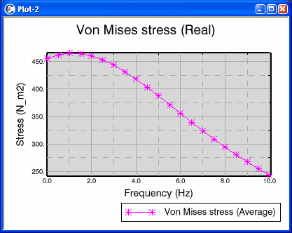
To visualize the sensor in a XY plot, right-click a local sensor, and select Open 2D Display.
A plot window appears. You can modify the plot options, the chart options, the curve options, or the axis options. Example of a XY plot for a Von Mises stress local sensor:

|