Generating Images | ||||||
|
| |||||
Select the desired set or the desired entity in the specification tree, and click Generate Images
 .
.A contextual menu is also available
 .
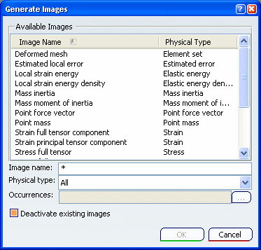
.The Generate Images dialog box appears.

The list of the available images varies depending on the selected set or entity. See Available Images. By default, the images are listed in an alphabetic order.Select one or several images in the list. You can reorder or filter the list according to the image name, the physical type.
- To change the list order, select the Image Name menu.
- In the Image name box, you can enter the name of an image to filter the list. For example, enter *mises* in the Image name box and press Enter. The list of available images is reduced to the image whose name contains the string mises.
- In the Physical type list, select a physical type to filter the list of images according to their physical type.
- Sub Types: lets you filter the available images according to the sub-types.
Optional: For multi-occurrence solutions, you can select the occurrences you want to create. Multi-selection of occurrences is available. An image will be generated for each selected occurrences (if you select three occurrences you will then generate three images). To select the occurrences:
- Enter the list of the desired occurrences. If you enter 1,6-8 as Occurrences values, the selected occurrences are: 1, 6, 7 and 8.
- Or click the ... button, press and hold down the Ctrl key, and select the desired occurrences.
Optional: To deactivate automatically the existing images, select the Deactivate existing images check box.
Click OK.
The image is generated, is visualized in the 3D window and an image feature is created in the specification tree. The corresponding color map appears (except for deformed mesh images). For images of multi-occurrence solutions, the current occurrence and its associated value are displayed in the color map.
If you selected several images or if you selected several occurrences of an image, several images are generated and the visualization of those images is superimposed.