Creating a Prismatic Roughing Operation | ||||
|
| |||
Create the Operation
This procedure shows you how to create a Roughing operation using Prismatic Roughing command.
Activate the Manufacturing Program and click Prismatic Roughing
 in the Prismatic Machining Operations toolbar.
A Prismatic Roughing entity is added to the Manufacturing Program.
in the Prismatic Machining Operations toolbar.
A Prismatic Roughing entity is added to the Manufacturing Program.The Prismatic Roughing dialog box appears directly at the Geometry tab
 .
This tab includes a sensitive icon to
help you specify the
geometry.
.
This tab includes a sensitive icon to
help you specify the
geometry.
 By default,
areas of the icon are colored red indicating that this
geometry is required.
By default,
areas of the icon are colored red indicating that this
geometry is required. Select the Strategy tab
 to set the machining parameters, radial and axial stepover conditions, HSM, and user parameters.
- If you have selected a Back and forth tool path style, click the arrow in the sensitive icon to modify the proposed tool axis direction, if necessary.
- If needed, click the tool axis symbol to invert the tool axis direction. See Defining the Tool Axis
Go to the Tool tab
 to select a tool.
Only end mill tools can be used in Prismatic Roughing operations.
Select the Feeds and Speeds tab
 to specify the feedrates
and spindle speeds for the operation.
to specify the feedrates
and spindle speeds for the operation. Select the Macros tab
 to specify the operation NC Macros
(approach and retract motion, for example).
to specify the operation NC Macros
(approach and retract motion, for example).Click Tool Path Replay
 to check the validity of the operation.
- The tool path is computed.
- A progress indicator is displayed.
- You can cancel the tool path computation at any moment before 100% completion.
![]()
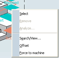
Select Planar Surfaces as Imposed Planes
You can use the Search/View contextual command to find all of the planar surfaces in the part or only the planes that can be reached by the tool you are using and use them as imposed planes.
Right-click Imposed in the sensitive icon and select Search/View in the contextual menu.
In the dialog box that appears:
- Click either All planes or Reachable planes.
The dialog box is populated.
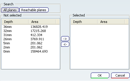
- Click either All planes or Reachable planes.