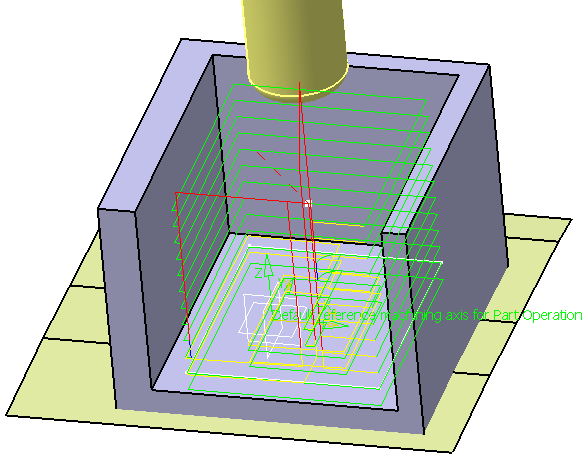
Prismatic Roughing | ||
| ||
![]()
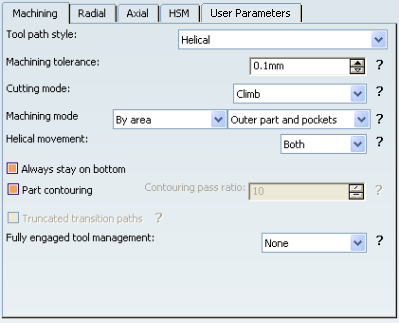
Machining Parameters
Note: The tabs User Parameters and Output require specific conditions to be displayed.
- Tool path style
- Specifies the tool path style.
The options in the Tool path style dropdown combo box are as follows:
- Machining tolerance
- Specifies the maximum allowed distance between the theoretical and computed tool path. Consider the value to be the acceptable chord error.
- Cutting mode
- Specifies the position of the tool regarding the surface to be machined.
The options in the Cutting mode dropdown combo box are as follows:
- Climb:
- Conventional:
- Climb:
- Machining mode
- Defines the type of area to be machined.
The options in the Machining mode dropdown combo box are as follows:
- By plane: the whole part is machined plane by plane
- By area: the whole part is machined area by area
then
- Pockets only: only pockets on the part are machined
- Outer part: only the outside of the part is machined
- Outer part and pockets: the whole part is machined outer area by outer area and then pocket by pocket.
- Helical movement
- Specifies the way the tool moves in a pocket or an external zone. This is available for Helical tool path style.
The options in the Helical movement dropdown combo box are as follows:
- Inward: the tool starts from a point inside the zone and
follows inward paths parallel to the boundary.
- Outward: the tool starts from a point inside the zone and
follows outward paths parallel to the boundary.
- Both: For pockets, the tool starts from a point inside the
pocket and follows outward paths parallel to the boundary.
For external zones, the tool starts from a point on the rough stock boundary
and follows inward paths parallel to the boundary.

- Inward: the tool starts from a point inside the zone and
follows inward paths parallel to the boundary.
- Always stay on bottom
- When this check box is selected, the linking path between two areas remains in the plane currently machined . This is available for Helical tool path style.
- Part contouring
- When selected, lets the tool machine the outside contour of the part before roughing.
- Contouring pass ratio
- Specifies the position of the final pass for removing scallops. This is done by entering a percentage of the tool diameter (0 to 50). This is available for Back and Forth tool path style.
- Truncated transition paths
- Enables the tool to follow the external profile more exactly by allowing
the transition portion of the trajectory to be truncated. this is available for Back and Forth tool path style.
- Truncated transition paths is selected:
- Truncated transition paths is not selected:
- Truncated transition paths is selected:
- Fully engaged tool management
- Manages full material cut when roughing hard material,
where the stepover is not always respected and where the tool can be damaged.
This can be avoided by switching to a trochoid motion that reduces the stepover,
or by adding machining planes to reduce the load on the tool.
Full engagement is detected when:
- More that 75% of the tool diameter is engaged in the material
- or More than 120 degrees of the tool is in contact with the material
The options in the Fully engaged tool management dropdown combo box are as follows:
- None: No management of the tool engagement.
- Trochoid: Adds a trochoid motion in areas where the stepover
is not respected. The trochoid motion is managed by
- the
Minimum trochoid radius:

 By default,
the Minimum trochoid radius value is 1mm.
By default,
the Minimum trochoid radius value is 1mm. - the Max engagement.
By default,
the Max engagement value is 0.5mm.
- the
Minimum trochoid radius:
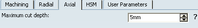
- MultiPass: Adds machining planes in areas where the stepover is not respected. The distance between those additional planes is managed by the parameter Maximum full material cut depth. In previews and replays, a warning is displayed if this cut depth is greater than the Maximum cut depth.

![]()
Radial Parameters
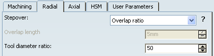
- Stepover
The options in the Stepover dropdown combo box are as follows:
- Overlap ratio: the overlap between two passes, given as a
percentage of the tool diameter.
- Overlap length: the overlap between two passes, given as
a distance.
- Stepover ratio: the stepover between two passes, given as
a percentage of the tool diameter.
- Stepover length: the stepover between two passes, given as
the maximum distance between passes.
- Overlap ratio: the overlap between two passes, given as a
percentage of the tool diameter.
- Tool diameter ratio
- Specifies the tool diameter ratio. This is available when Overlap ratio is selected as Stepover.
![]()
HSM Parameters
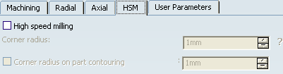
- High Speed Milling
- Specifies whether or not cornering for HSM is done on the trajectory.
- Corner radius
- Specifies the radius used for rounding the corners along the trajectory of
a HSM operation.
The tool path is rounded to give a smoother path that can be machined faster. The minimum value of the corner radius is the radius of the tool.
Note: Value must be smaller than the tool radius.
- Corner radius on part contouring
- Specifies the radius used for rounding the corners along the part contouring
pass of a HSM operation.
Note: This radius must be smaller than the value set for the Corner radius.
![]()
Output
This tab is displayed when the check box2D circular interpol is selected in the Numerical Control tab of the machine. See NC Manufacturing Infrastructure User's Guide: Assigning a Machine with the Machine Editor
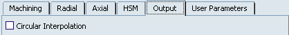
- Circular Interpolation
- When selected, lets you generate an arc interpolation output when the tool is in contact with a revolution surface (but not with one represented by a CATNurbsSurface). This arc will be propagated to radial paths created by offset of this path, when they exist.
By default,
this check box is not selected.
![]()
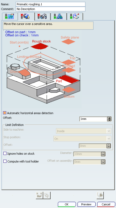
Geometry
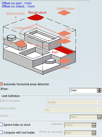
You can specify the following geometry:
- Part with possible offset.
- Rough stock, which is required.
Note: The stock used in Prismatic Roughing must be fully defined and closed (like a solid). Deviation to this policy may lead to inaccurate tool path computation (potential collision) and to error during video simulation. Therefore, it is not accepted.
- Check element with possible offset. The check element is often a clamp that holds the part and therefore is not an area to be machined.
- Safety plane, which is the plane that the tool rise to at the end of the tool path in order to avoid collisions with the part. You can also define a new safety plane with the Offset option in the safety plane contextual menu. The new plane is offset from the original by the distance that you enter in the dialog box.
- Top plane which defines the highest plane that can be machined on the part.
- Bottom plane which defines the lowest plane that can be machined on the part.
- Imposed plane that the tool must pass through. Use this option if the part that you are going to machine has a particular shape (a groove or a step) that you want to be sure can be cut. See Creating a Prismatic Roughing Operation for more information.
- Start point where the tool is to start cutting.
- When drilling holes exist, defining start points implies that you set Mode in
the NC macros tab to Radial only to avoid any plunge or
ramping macros. If a radial engagement is not possible (collision with
part or with the residual material), the roughing tool path is stopped.
Note: If you leave Mode to Plunge, no control is carried out when the tool can plunge at the start point. If the start point is not correct or if no start point has been defined for a given area, no start point is computed automatically and the tool plunges in material.
- When drilling holes exist, defining start points implies that you set Mode in
the NC macros tab to Radial only to avoid any plunge or
ramping macros. If a radial engagement is not possible (collision with
part or with the residual material), the roughing tool path is stopped.
- Start points:
- Manage contouring passes,
- Manage outer part and pockets (therefore, you do not need to deactivate previous drilling operations),
- Are taken into account if they lie inside the drilling hole (even if they are not completely outside the part, check surfaces or rough stock),
- Have a contextual menu:
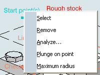
- Maximum radius
- For each start point, the point to join after the start point
must lay in a circle defined by a maximum radius. Maximum radius in the contextual menu starts the dialog box to activate and define this radius.
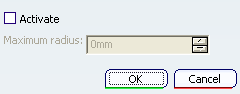
Select the Activate check box to take the maximum radius into account.
By default,
Activate is not selected, no maximum radius is applied to the
start points, all start points are taken into account whether they lie
within the circle or not. - Plunge on point
- Makes the plunge of the tool at the start point compulsory. When this command is not selected, the tool cannot plunge at the start point. The start point can only impose the direction of the radial engagement.
- For Helical Tool path style, whenever possible, the end of the engagement associated to the start point corresponds to the beginning of the sweeping path.
- Limiting contour which defines the machining limit on the part, with the Side to machine parameter.
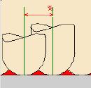
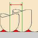
- Automatic horizontal areas detection
- When this check box is not selected, the only way to ensure that a cutting plane
corresponds with an horizontal area is to define an Imposed plane crossing
the area. This means that you have to consider the offset on part. This plane
applies to the whole part (which is not necessary). If there are several horizontal
areas to consider at different levels you have to define all of the corresponding
Imposed planes (black planes in the figure below, orange planes are standard
planes).
- When this check box is selected, you can:
- Detect automatically horizontal areas on the part,
- Limit the cutting plane effect to these areas,
- Apply a dedicated offset on the part for these areas,
- Define the Maximum angle that can be considered as horizontal. The angle is measured perpendicular to the tool path.
If the machining mode is:
- By area, the tool path looks like
this:
- By plane, the tool path looks like
this:
The cutting planes in green are the standard roughing tool paths, the red ones are those computed for the horizontal areas detected.
Note:
- The computation of horizontal areas is not possible if the part is made of a cloud of points (STL).
- This option is not compatible with the use of offset groups.
- This option is not compatible with the option Compute with tool holder in the Geometry tab.
- Horizontal areas are always defined as pockets (no distinction outer part/pocket). To mill pockets or outer part areas, use a limiting contour.
- When only outer part areas are to be machined, no specific tool path style is given for the pockets. As a consequence, if the tool path style used for the outer part areas is not compatible with pockets (e.g. By Offset on part with One-Way), horizontal areas are machined with a default tool path style (Concentric).
- In circular interpolation output mode, circles cannot be created on horizontal areas. This may lead to some desynchronization with the areas above. When such a situation is detected, the horizontal area is removed to avoid overcut with the tool.
- When this check box is not selected, the only way to ensure that a cutting plane
corresponds with an horizontal area is to define an Imposed plane crossing
the area. This means that you have to consider the offset on part. This plane
applies to the whole part (which is not necessary). If there are several horizontal
areas to consider at different levels you have to define all of the corresponding
Imposed planes (black planes in the figure below, orange planes are standard
planes).
- Offset
- Defines the distance that the tool can overshoot the Position. It is expressed as a percentage of the tool diameter. This parameter is useful in cases where there is an island near the edge of the part and the tool diameter is too wide to allow the area behind the island to be machined. This parameter can only be used if the Position is Inside or Outside.
- Limit Definition
- Defines what area of the part can be machined with respect to limiting contours.
It can either be inside or outside. In the pictures below, there are three
limiting contours on the rough stock. The yellow areas can be machined:
- Limit the Machining Area
- With R210 release, the tool motion is added along limit line on both sides, to remove
residual material around the limit line and secures the machining on
lower levels. Now, there is no collision between the residual material
and toolholder and height of removed material is also not greater
than the distance between levels.
The machining trajectory is more secure because of these paths and removes residual material on both sides before machining the bottom.
- Ignore holes on stock
- When selected, ignores holes which are on the rough stock. Once this check box is selected, define the diameter value below which holes are to be ignored.
- Compute with tool holder
 .
.![]()
Feedrates and Speeds Parameters
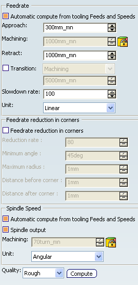
- Feedrate: Automatic compute from tooling Feeds and Speeds
- This check box allow an operation's feeds and speeds values to be updated automatically when the tool's feeds and speeds values are modified.
You can specify the following feedrates:
- Approach
- Machining
- Retract
Note:
The above feedrates can be defined in linear (feed per minute) or angular (feed per revolution) units.
- Angular: feedrate in revolutions per minute and unit is set to mm_turn.
- Linear: feedrate in feed per minute and unit is set to mm_mn.
- Transition
- You can locally set the feedrate for a transition path to a
machining operation B from a machining operation A or from a tool
change activity. This is done by selecting the Transition check box in the Machining Operation dialog box for
operation B.
For more information, please refer to the Setting a Transition Feedrate.
- Slowdown Rate
- Reduces the current feedrate by a given percentage.
The reduction is applied to the first channel cut and to
the transitions between passes:
- In Helical tool paths, the reduction is applied to the first channel cut.
- In Back and Forth tool paths, the reduction is applied to the first channel cut and to the transitions between passes.
- Feedrate Reduction in Corners
- You can reduce feedrates in corners encountered along
the tool path depending on values given in the Feeds and Speeds
tab page:
- Reduction rate
- Maximum radius
- Minimum angle
- Distance before corner
- Distance after corner
Feed reduction is applied to corners along the tool path whose radius is less than the Maximum radius value and whose arc angle is greater than the Minimum angle value.
When machining pockets, feedrate reduction applies to inside and outside corners for machining or finishing passes. It does not apply for macros or default linking and return motions.
Corners can be angled or rounded, and may include extra segments for HSM operations.
- Combining Slowdown Rate and Feedrate Reduction in Corners
If a corner is included in a slowdown path, the general rule is that the lowest percentage value is taken into account. For example:
- if the Slowdown rate is set to 70% and Feedrate reduction rate in corners is set to 50%, the feedrate sequence is: 100%, 70% (entry in slowdown), 50% (entry in corner), 70% (end of corner, still in slowdown), 100% (end of slowdown).
- If feedrate Reduction rate in corners is then set to 75%, the feedrate sequence is: 100%, 70% (entry in slowdown), 70% (entry in corner: 75% ignored), 70% (end of corner, still in slowdown), 100% (end of slowdown).
- Spindle Speed: Automatic compute from tooling Feeds and Speeds
This check box allow an operation's feeds and speeds values to be updated automatically when the tool's feeds and speeds values are modified.
If the Feedrate Automatic compute check box is selected and the Spindle Speed: Automatic compute from tooling Feeds and Speeds check box is not selected, then only the feedrate values can be computed. If both are not selected then automatic updating is not done.
When you modify a tool's feeds and speeds, all existing operations with the Automatic compute check boxes selected that use this tool (or an assembly using this tool) can be recomputed.
- Spindle output
- This check box manage output
of the SPINDL instruction in the generated NC data file:
- If the check box is selected, the instruction is generated.
- Otherwise, it is not generated.
Note:
The spindle speed can be defined in linear (length per minute) or angular (length per revolution) units.
- Angular: length in revolutions per minute and unit is set to mm_turn.
- Linear: length in feed per minute and unit is set to mm_mn.
- Quality
- The feed and speed values are computed according to the Quality setting on the operation.
- Compute
- Feeds and speeds of the operation can be updated according to tooling feeds and speeds by clicking the Compute button located in the Feeds and Speeds tab of the operation.
Feeds and speeds of the operation can be updated automatically according to tooling data and the rough or finish quality of the operation. This is described in About Feeds and Speeds.
![]()
NC Macros
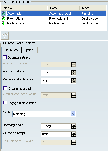
The following types of macro can be defined on a Prismatic Roughing operation:
- Pre-Motion Macros: These macros are built using the elementary motions proposed in the Current Macro Toolbox. A pre-motion macro is applied between the rapid motion from safety plane and the automatic macro.
- Post-Motion Macros: These macros are built using the elementary motions proposed in the Current Macro Toolbox. The post-motion macro between the automatic macro and the rapid motion from safety plane.
- Automatic Roughing Macros: You must select one of the following approach modes to specify
how the tool can engage the material.
- Plunge: the tool plunges vertically.
- Ramping: the tool moves progressively down at the ramping
angle. Ramping approach mode applies to pockets but also to outer areas in
given conditions:
- If a limit line is used, the tool can approach outer areas of the part and pockets in ramping mode.
- If a lateral approach is not possible (due to the check element), the approach is made in ramping mode.
- Helix: the tool moves progressively down at the ramping angle with its center along a (vertical) circular helix of Helix diameter.
- Radial Only: When drilling holes exist, define start points and this mode to avoid any plunge or ramping macros. If a radial engagement is not possible (collision with part or with the residual material), the roughing tool path is stopped.
- Optimize retract
- When selected, optimizes tool retract movements. This means that
when the tool moves over a surface where there are no obstructions, it does not rise as high as the safety plane because there is no danger of tool-part
collisions. The result is a gain in time.
Note: In some cases (where areas of the part are higher than the zone you are machining and when you are using a safety plane), the tool may cut into the part. In this case, deselect the Optimize retract check box.
- Approach distance
- Engagement distance for the selected approach mode.
- Radial safety distance
- Distance that the tool moves horizontally before it begins its approach.
- Circular approach
- When selected, creates circular engagements from external
zones, with the given Circular approach radius:
- A cornering arc is inserted in the approach movements.
- All the movements can be tangent except when a collision could occur between the arc and the part.
- Engage from outside
- In case of open pockets, when selected creates engagements from external zones.
- Limitations on Circular approach and Engage from outside
- By default, the point used for external engagement is the point on the rough stock closest to the pattern start point.
- In case of collision, V6 tries to compute a pattern avoiding collision.
- If some collisions remain in planes you have defined, you can define a start point to help find out a pattern which avoids the collision.
- If some collisions remain in some planes even with the defined start point, a ramping approach can be created.