Probing Holes | |||||
|
| ||||
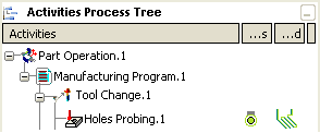
Activate the Manufacturing Program and click Holes or Pins Probing
 in the Prismatic Machining Operations toolbar.
A Hole Probing entity is added to the Manufacturing Program. The Holes Probing dialog box opens at the Geometry tab page
 .
This tab includes a sensitive icon to
help you specify the
geometry.
Areas of the icon are colored red indicating that this
geometry is required.
.
This tab includes a sensitive icon to
help you specify the
geometry.
Areas of the icon are colored red indicating that this
geometry is required. 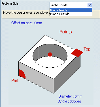
Still in the Geometry tab:
-
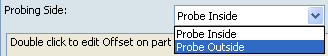
Select the Probing Side.
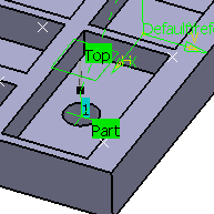
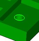
- Similarly, click Points in the sensitive icon and select the edge of the hole in the authoring window.
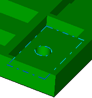
- Click Top and select the plane around the hole.
-
Select the Probing Side.
Select the Strategy tab
 to specify the strategy and user parameters.
Go to the Tool tab
 to select a tool.
Select the Feeds and Speeds tab
 to specify the feedrates
and spindle speeds for the operation.
to specify the feedrates
and spindle speeds for the operation.Select the Macros tab
 to specify the desired
transition paths.
to specify the desired
transition paths. Click Tool Path Replay
 to check the validity of the operation.
- The probing tool path is computed.
- A progress indicator is displayed.
- You can cancel the tool path computation at any moment before 100% completion.
Click OK in the Tool Path Replay dialog box, and again in the main dialog box.
The probing tool path is created.