Creating a 4-Axis Pocketing Operation | |||||
|
| ||||
Create the Operation
You can use 4-axis Pocketing command to create the 4-Axis Pocketing operation.
Activate the Manufacturing Program and click 4-axis Pocketing
 in the Prismatic Machining Operations toolbar.
A 4-axis Pocketing entity is added to the Manufacturing Program.
The 4-axis Pocketing dialog box appears directly at the Geometry tab
 .
.The bottom and flanks of the icon are colored red indicating that this geometry is required for defining the pocket. All other pocket geometry is optional.
Still in the Geometry tab:
- Click red Bottom then select the desired pocket
bottom in the authoring window.
Note: The bottom for 4-axis Pocketing operation must be a convex surface.
The pocket boundary is automatically deduced thanks to the Contour Detection setting. This is indicated by the highlighted Drive elements.
The bottom and flanks of the icon are now colored green indicating that this geometry is now defined.
- Click red Bottom then select the desired pocket
bottom in the authoring window.
- Choose a Tool Path Style.
- Set the parameters for machining, radial and axial strategy, finishing, HSM, and user parameters.
Go to the Tool tab
 to select a tool.
Select the Feeds and Speeds tab
 and specify the feedrates
and spindle speeds for the operation.
and specify the feedrates
and spindle speeds for the operation.Select theMacro tab
 and add approach and retract motions to the operation.
See Defining Macros on Milling Operations
Click Tool Path Replay
 to check the validity of the operation.
- The tool path is computed.
- A progress indicator is displayed.
- You can cancel the tool path computation at any moment before 100% completion.
 :
:![]()
Specify the Pocket Boundary
You can specify the pocket boundary in different ways. The pocket boundary must be closed.
-
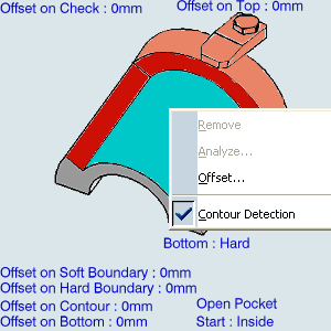
- Right-click the pocket in the sensitive icon and select
Contour Detection in the contextual menu, then select the pocket bottom in the authoring window.
- or select edges in the sensitive icon and use the Selecting Edges and Faces to Define Geometry toolbar that appears to specify the pocket boundary in the authoring window.
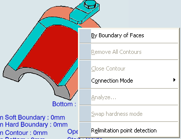
- or right-click the edges in the sensitive icon and select the By Boundary of Faces in the contextual
menu and use the
Selecting Edges and Faces to Define Geometry toolbar that appears to specify the
pocket boundary in the authoring window.
- Right-click the pocket in the sensitive icon and select
Contour Detection in the contextual menu, then select the pocket bottom in the authoring window.