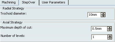
Trochoid Milling | |||||
|
| ||||
![]()
Machining Parameters
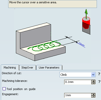
- Direction of cut
- Specifies how machining is to be done.
- Climb milling: the front of the advancing tool (in the machining direction) cuts
into the material first.
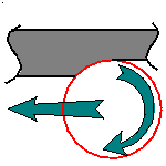
- Conventional: the rear of the advancing tool (in the machining direction) cuts
into the material first.
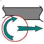
- Climb milling: the front of the advancing tool (in the machining direction) cuts
into the material first.
- Machining tolerance
- Specifies the maximum allowed distance between the theoretical and computed tool path.
- Tool position on guide
- Specifies the position of the tool tip on the guiding element.
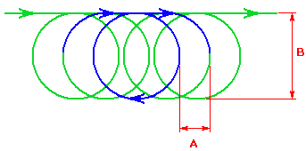
- Engagement
- Specifies
the engagement (A in below image) of the tool during trochoidal motion.
![]()
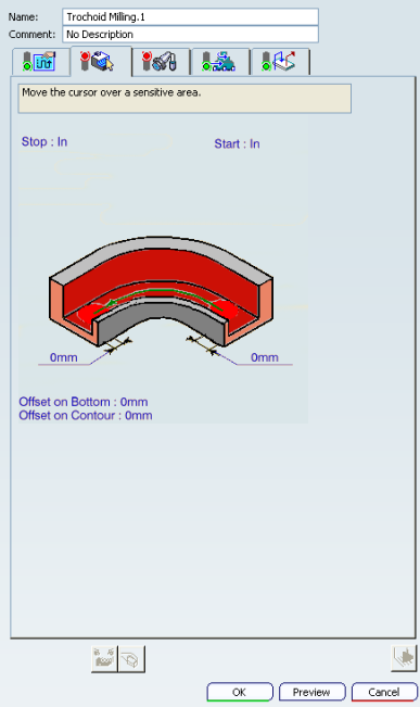
Geometry
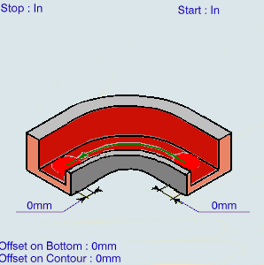
You can specify the following Geometry:
- Bottom (planar face or surface) with possible Offset on Bottom.
- Guide contour (edges only) with possible Offset on Contour.
- Start and Stop relimiting elements with possible offsets.
![]()
Feedrates and Speeds Parameters
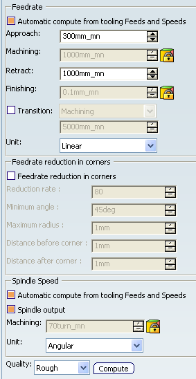
- Feedrate: Automatic compute from tooling Feeds and Speeds
- This check box allow an operation's feeds and speeds values to be updated automatically when the tool's feeds and speeds values are modified.
You can specify the following feedrates:
- Approach
- Machining
- Retract
- Finishing
Note:
The above feedrates can be defined in linear (feed per minute) or angular (feed per revolution) units.
- Angular: feedrate in revolutions per minute and unit is set to mm_turn.
- Linear: feedrate in feed per minute and unit is set to mm_mn.
- Transition
- You can locally set the feedrate for a transition path to a
machining operation B from a machining operation A or from a tool
change activity. This is done by selecting the Transition check box in the Machining Operation dialog box for
operation B.
For more information, please refer to the Setting a Transition Feedrate.
- Feedrate Reduction in Corners
You can reduce feedrates in corners encountered along the tool path depending on values given in the Feeds and Speeds tab page:
- Reduction rate
- Minimum angle
- Maximum radius
- Distance before corner
- Distance after corner

Feed reduction is applied to corners along the tool path whose radius is less than the Maximum radius value and whose arc angle is greater than the Minimum angle value. Corners can be angled or rounded.
For Trochoid Milling, feedrate reduction applies to inside corners. It does not apply for macros or default linking and return motions.
If a cornering is defined with a radius of 5mm and the Feedrate reduction in corners set to a lower radius value, the feedrate cannot be reduced.
Note: Trochoid milling is an operation that allows to machine hard materials, using a small engagement step. Feedrate reduction cannot be applied to small distances, and thus does not affect trochoid milling.
- Spindle Speed: Automatic compute from tooling Feeds and Speeds
This check box allow an operation's feeds and speeds values to be updated automatically when the tool's feeds and speeds values are modified.
If the Feedrate Automatic compute check box is selected and the Spindle Speed: Automatic compute from tooling Feeds and Speeds check box is not selected, then only the feedrate values can be computed. If both are not selected then automatic updating is not done.
When you modify a tool's feeds and speeds, all existing operations with the Automatic compute check boxes selected that use this tool (or an assembly using this tool) can be recomputed.
- Spindle output
- This check box manage output
of the SPINDL instruction in the generated NC data file:
- If the check box is selected, the instruction is generated.
- Otherwise, it is not generated.
Note:
The spindle speed can be defined in linear (length per minute) or angular (length per revolution) units.
- Angular: length in revolutions per minute and unit is set to mm_turn.
- Linear: length in feed per minute and unit is set to mm_mn.
- Quality
- The feed and speed values are computed according to the Quality setting on the operation.
- Compute
- Feeds and speeds of the operation can be updated according to tooling feeds and speeds by clicking the Compute button located in the Feeds and Speeds tab of the operation.
Feeds and speeds of the operation can be updated automatically according to tooling data and the rough or finish quality of the operation. This is described in About Feeds and Speeds.
![]()
NC Macro
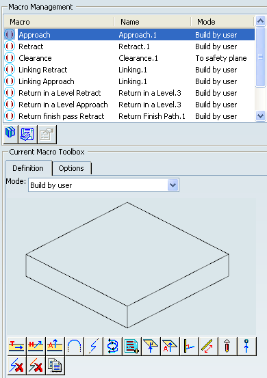
You can define transition paths in your machining operations by means
of NC macros:
- Approach: to approach the operation start point,
- Retract: to retract from the operation end point,
- Linking:
- to link two non consecutive paths
- to access finish and spring passes.
- Return in a Level to link two consecutive paths in a given level in a multi-path operation
- Return between Levels to go to the next level in a multi-level machining operation,
- Return to Finish Pass to go to the finish pass
- Clearance to avoid a fixture, for example.
The proposed macro mode are:
- None
- Build by user
- Circular horizontal axial
- Horizontal horizontal axial
- Axial
When a collision is detected between the tool and the part or a check element, a clearance macro is applied automatically. If applying a clearance macro would also result in a collision, then a linking macro is applied. In this case, the top plane defined in the operation is used in the linking macro. The top plane element must be selected in order to apply an automatic linking macro without collision. See Defining Macros.
