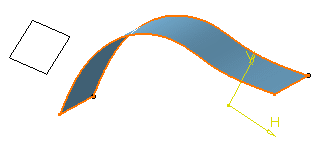
Select the surface you want
to extrude.
The different surfaces you can select are:
- surfaces created in the Generative Shape Design workbench
- Version 4 surfaces
- non-planar faces.

Click Pad
 in the Sketch-Based Features toolbar (Pads sub-toolbar).
The Pad Definition dialog box appears.
You need to define an extrusion direction. To do so, either
you select a geometric element or set the Up to Plane
limit and select the plane of your choice. In that case, the
direction will be given by the normal to that plane (for more,
see pockets).
Click the Reference box and select the plane
you want to define the extrusion direction. The direction is the normal
to the plane.

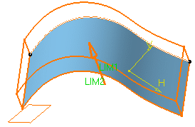
Enter 21mm and 11mm as the first and second limit values
respectively.
Click OK to confirm.
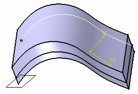
The new element identified as Pad.XXX
is added to the specification tree.If
you create a pad or a pocket from a non-planar face, that face
is displayed as a
datum in the specification tree.
