Creating or Editing a Lathe Tool | |||||||
|
| ||||||
Create a Lathe Tool with both Insert Holder and Insert
You can create a lathe tool from the Tool Builder toolbar. A lathe tool is a sub-assembly made of an insert holder and an insert.
From any product:
- Alternatively, open an existing Machining Process or PPR context .
 By default,
the
Activities Process Tree opens
automatically.
By default,
the
Activities Process Tree opens
automatically.
- Alternatively, open an existing Machining Process or PPR context .
If the Tool Builder toolbar is not visible, select
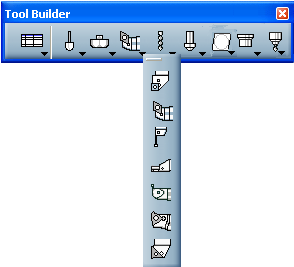
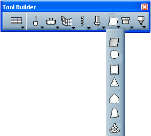
The Tool Builder toolbar is displayed. The icons used to create a lathe tool are found in the Lathe Tools sub-toolbar:
See Multi-slide Lathe Machining: Managing Machining Resources for more information.
Click the icon corresponding to the lathe tool you want to create.
The Lathe Tool Creation dialog box is displayed. It contains:
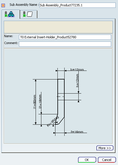
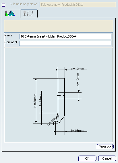
In the Insert Holder tab:
- Double-click any value in the icon representing the geometry of the Insert Holder to edit it in the dialog box that appears.
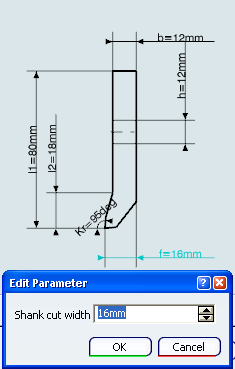
The representation icon is updated with the new values.
- Double-click any value in the icon representing the geometry of the Insert Holder to edit it in the dialog box that appears.
Go to the Geometry
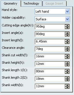
or the Technology tab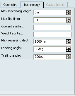
and edit the parameters as requested.The representation icon is updated with the new values.
Go to the Compensation tab and enter the desired values for the tool compensation parameters.
- Use the contextual menu to add, edit or delete an existing compensation site.
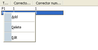
- Use the contextual menu to add, edit or delete an existing compensation site.
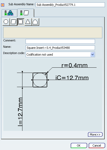
Go to the Insert tab.
Go to the Geometry
or the Technology tab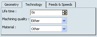
and edit the parameters as requested.The representation icon is updated with the new values.
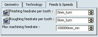
Go to the Feeds & Speeds tab to define those parameters.
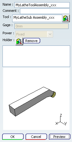
Click OK to create the lathe tool and exit the dialog box.
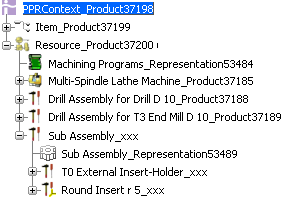
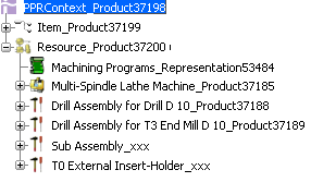
It is added to the Machining Cell as Sub Assembly_xxx with new insert holder T0 External Insert-Holder_xxx and an insert Round Insert r5_xxx.
Note: Lathe operations take into account tool assemblies only:
- create a lathe tool, as described above.
- then create a tool assembly, in which you insert the lathe tool. See Create a Lathe Tool Assembly
![]()
Create a Single Insert Holder without Insert
You can create a insert holder from the Tool Builder toolbar.
Un-select the Sub Assembly Name check box.
The Insert Holder tab is available and Insert tab is disabled.
In the Insert Holder tab:
- Double-click any value in the icon representing the geometry of the Insert Holder to edit it in the dialog box that appears.
The representation icon is updated with the new values.
- Double-click any value in the icon representing the geometry of the Insert Holder to edit it in the dialog box that appears.
Go to the Geometry
or the Technology tab
or theGauge Insert tab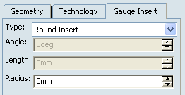
and edit the parameters as requested.The representation icon is updated with the new values.
By default,
insert holder is supported with Round Insert.Go to the Compensation tab and enter the desired values for the tool compensation parameters.
- Use the contextual menu to add, edit or delete an existing compensation site.
- Use the contextual menu to add, edit or delete an existing compensation site.
Click OK to create the lathe tool and exit the dialog box.
insert holder T0 External Insert-Holder_xxx is created.
![]()
Create a Lathe Insert
You can create a lathe insert from the Tool Builder toolbar.
From any product:
- Alternatively, open an existing Machining Process or PPR context .
By default,
the
Activities Process Tree opens
automatically.
- Alternatively, open an existing Machining Process or PPR context .
If the Tool Builder toolbar is not visible, select
The Tool Builder toolbar is displayed. The icons used to create a lathe insert are found in the Lathe Insert tool sub-toolbars:
Click the icon corresponding to the insert you want to create.
The Insert Definition dialog box is displayed.
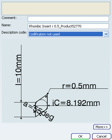
- Double-click any value in the icon representing the geometry of the
Insert
to edit it in the dialog box that appears.
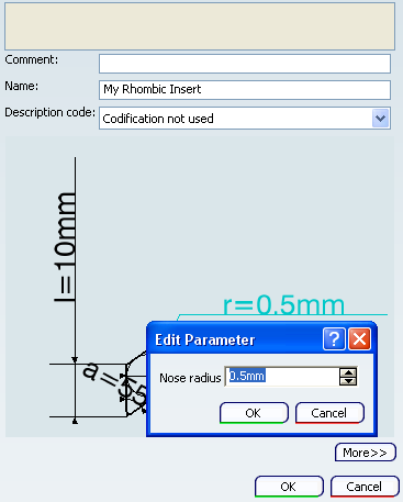
The representation icon is updated with the new values.
- Double-click any value in the icon representing the geometry of the
Insert
to edit it in the dialog box that appears.
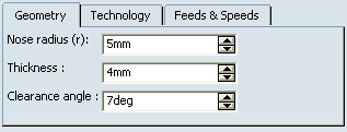
Go to the Geometry
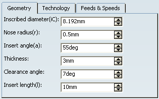
or the Technology tab
and edit the parameters as requested.The representation icon is updated with the new values.
Go to the Feeds & Speeds tab to define those parameters.
Click OK to create the lathe insert tool and exit the dialog box.
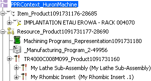
It is added to the Machining Cell as My Rhombic Insert.
![]()
Edit Lathe Insert and Insert Holder
You can edit a lathe insert and Insert holder from the Machining Cell.
Right-click a lathe insert and insert holder in the Machining Celland select
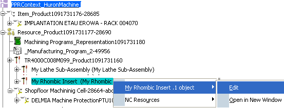
or double-click the insert and insert holder in the PPR Context.
![]()
Create a Lathe Sub-assembly with Shank and Insert from Database
You can create a lathe sub-assembly from the Tool Builder toolbar.
Click Lathe Tool
 .
.The Sub Assembly creation dialog box appears.
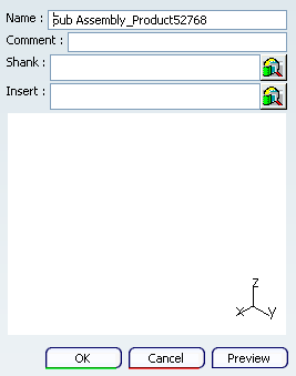
Click
 and select a shank (insert holder) and insert in the dialog box that appears.
Note: The selected shank and the insert must be compatible.
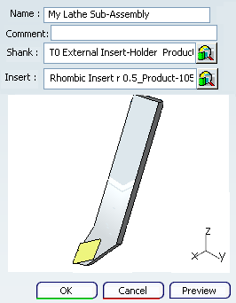
Click OK to create the MyLatheSub-Assembly_xxx and exit the dialog box.
The MyLatheSub-Assembly_xxx is created under the Machining Cell
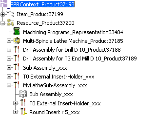
 .
.