About Representation Management | |||||||
|
| ||||||
When you create a tool, a tool holder or
tool assembly, geometrical representations of those elements are created as 3D Parts.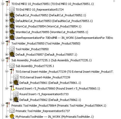
- In most cases, the representation is created automatically, with the prefix Default.
- For drill tools, end mill tools, face mill tools, conical mill tools and T-Slotter, you can create the tool with a maximum wear definition. In this case, additional representations are added with the prefix Worn. See Taking Maximum Wear Cutting Condition into Account.
- When you create a prismatic tool holder, you need to associate the representation to the tool holder. See Creating or Editing a Tool Holder.
- You can create an user representation of a tool, a tool holder or tool assembly and associate this representation.
The representation:
- contains a Base Axis and a Mount Axis, used for the instantiation in an assembly.
- is recomputed each time to edit the associated tool, tool holder or tool assembly.
Note: you cannot modify an automatic representation (i.e. one with the prefix Default or Worn) nor its axes, but you can create a user representation.
During simulations:
- if only Default representations exist, they are used.
- if user representations exist (and have been declared as such), they have priority and are used in place of the Default representations.
- if Worn representations exist (and have been declared as such), they are used depending on the ISO Code Simulation selected. See Taking Maximum Wear Cutting Condition into Account.
Representations are managed from the contextual menu of the tool, tool holder or tool assembly . 
Note: Since the automatic representations are not editable, they are not displayed in the Manage Representation dialog box.
See Creating or Editing a Tool Holder for an example of operating mode.
- When a representation is selected as Static and Rotary : It is considered as Rotary.
- If a Rotary representation for one Type (Cut or No Cut) is defined, it replaces the Default representation.
- The Base Axis and the Mount Axis for a tool component must be found in a Part or Product instantiated under the tool component.
- When the Base Axis and the Mount Axis of a tool assembly are not defined, the Base Axis of the tool base axis and the Mount Axis of the last tool holder are taken into account.