Define the Wear Condition of the Tool
You can define maximum wear parameters when defining drill tools, end mill tools, face mill tools, conical mill tools, and T-Stlotters.
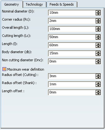
While defining one of the tools listed above, click More and go to the Geometry tab. - Select the Maximum wear condition check box.

- Define the three parameters linked to Maximum wear condition: Radius offset (Cutting), Radius offset (Shank), Length offset according to your needs.
 By default,
these parameters are set to 0. It is your responsability to decide which parameter must be defined, and to which value.
The Maximum wear condition with a length offset means the tool is shortened (the tool gauge is reduced). The reference point of the tool is computed starting from the Base axis with a Z offset corresponding to the Length offset value
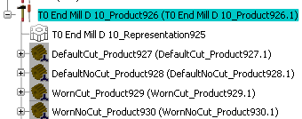
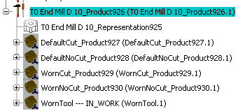
Click OK when done, to validate and exit the dialog box. The tool is created in the Machining Cell, with Defaultxxx representations and Wornxxx representations.

An alternative is to create an user representation of the worn tool. - Create the 3D Part with the requested geometry definition,
- The position of the representation must respect the aligment with the length offset.
- The shapes must be coherent regarding the radial offset.
- The coherence of the parameters, user representation and position of the representation are under your responsibility.
- Attach it to the tool. See About Representation Management.
In this user representation, you must set State to Worn and Rotary to Yes.


Define the Cutting Tool Condition for the Simulation
You can choose the cutting tool condition used for simulation.
Select .
Go to the Simulation tab.
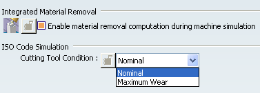
- Make sure the Enable material removal computation during simulation check box is selected.
- Select the Cutting Tool Condition for the simulation.

|