About NC Macros | |||||||
|
| ||||||
NC Macros in Machining Operations
You can use NC Macros to define a Transition Path between one Machining Operation and another. A Transition Path is useful for providing approach, retract, and linking motion in the tool path.
You build the macros using the interface provided under the Macros
tab
 in the Machining Operation dialog box.
Predefined Macros
These are made up from one or more
paths in a specific order:
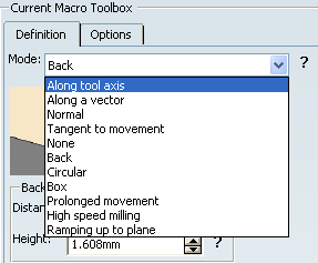
- You can select them from the Mode list under Current Macro
Toolbox of the Macros tab.
- You can then adjust parameters of the macro (such as path length and feedrate).
User-Built Macros
You can also build your own macros using the Build by user
mode and its icons.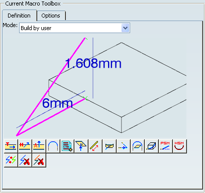
See Build by user
Proposed Macros

- Approach (1),
- Retract (2),
- Linking Approach (3),
- Linking Retract (4),
- Clearance,
- Between passes (5) (not available for Spiral Milling, Pencil),
- Between passes Link (not available for Spiral Milling, Pencil, ZLevel).
Note:
Between Passes has been split into Between
passes and Between passes Link. Between
passes Link corresponds to the highlighted portion of the
path below:

The macros are listed as follows:
- In the Macro column, you find the type of the macro,
- In the Name column, you find the name of the macro,
- In the Mode column, you find the machining mode of the macro.
 By default,
the application has affected a machining mode to
each macro. To affect another machining mode to a macro, select the
macro line under Macro Management,
then select a machining mode from the Mode list.
By default,
the application has affected a machining mode to
each macro. To affect another machining mode to a macro, select the
macro line under Macro Management,
then select a machining mode from the Mode list.
Here are the available modes:
For Approach, Retract, Between passes:
- Along Tool Axis
- Along a Vector,
- Normal,
- Tangent to Movement,
- None,
- Back,
- Circular,
- Box,
- Prolonged Movement,
- High Speed Milling (not available for Sweep Roughing, Spiral Milling, Pencil),
- Ramping up to Plane (Spiral Milling).
- Build by user.
For Linking Retract, Linking Approach:
- Along Tool Axis
- Along a Vector,
- Normal,
- Tangent to Movement,
- None,
- Back,
- Circular,
- Box,
- Prolonged Movement,
- High Speed Milling (not available for Sweep Roughing, Pencil),
- Ramping up to Plane (Spiral Milling).
- Defined by Approach/Retract, Defined by Approach
- Build by user.
For Clearance:
For Between passes Link (not available for Pencil):
- Straight,
- High Speed Milling (not available for Sweep Roughing),
- Prolonged Movement,
- Defined by Approach/Retract, Defined by Approach.
Inherited Macros
If you create a Machining Operation and there are other Machining Operations of the same type in the program, it inherit the macros used in the most-recently edited Machining Operation of the same type. A Machining Operation is considered edited when you click OK to quit the dialog box.
Cutter Compensation
For Pocketing, Profile Contouring, and Circular Milling operations, select the NC_CUTCOM_ON instruction in the list of available syntaxes if you want the program to interpret cutter compensation automatically (that is, by a CUTCOM/LEFT or CUTCOM/RIGHT instruction). If you choose a different syntax in the list, it can be used as selected. The methodology for this is described in Techniques: Procedure for Generating CUTCOM Syntaxes in Prismatic Machining User's Guide.
PP Words in Macros
You can insert PP words in macros by double-clicking the green X symbols in the sensitive icons.
The PP Words Selection dialog box is displayed. You can enter the syntax in the following ways:
- Enter one or more PP word syntaxes directly in the text field
- Click
 to access the PP words table that is referenced in the current Part Operation. You can then select predefined syntaxes from this table using
the dialog box that appears.
to access the PP words table that is referenced in the current Part Operation. You can then select predefined syntaxes from this table using
the dialog box that appears.
See Inserting PP Instructions for more information.
Successive PP Words
If the current macro ends with a PP word, PP word
 becomes inactive and so you cannot add another successive PP word. For example
in the following sequence of macro paths ending with PPword.2:
becomes inactive and so you cannot add another successive PP word. For example
in the following sequence of macro paths ending with PPword.2:
...-TangentMotion-PPWord.1-CircularMotion-PPWord.2
You cannot add another PP word directly after PPword.2. However, you can edit and complete PPWord.2.
when you insert a list of PP words in a tool path, the PP words appear in the tool path in the same order as in the list.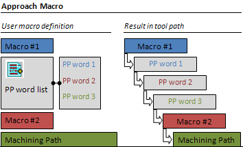

Macro Edition
A sensitive icon representing the elementary paths of the macro helps you to build or edit your macro.
Elementary Motions After an Axial Path
To edit a macro, use the contextual menu or:- in graphic mode:
- double-click a macro path or a geometry element to modify it.
- double-click a parameter label to display the edition dialog box to modify the value of this parameter only.
Note: since those dialog boxes are standard edition boxes, they are not shown below.
- In numeric mode:
- type the required value in the field,
- click the interrogation mark to launch the graphic help.
If the current macro ends with an axial path (Axial, Axial to a plane,
Axial perpendicular to a plane), the following icons become inactive:
 :
Tangent motion
:
Tangent motion :
Circular motion
:
Circular motion :
Normal motion
:
Normal motion :
Ramping motion
:
Ramping motion
This is because there is insufficient information about conditions such as tangency or normal to the axial path. This behavior is not applied to Surface Machining operations (the icons remain active).
Default Linking Macros in Case of Collision
If a user-defined linking macro is not collision free, a default linking macro is applied.
Macro Motion Tangent to Tool Path and Parallel to Tool Axis
When the tangent to the tool path is parallel to the tool axis, the following macro motions are replaced by an Axial motion:
- :
Tangent motion
- :
Circular motion
- :
Normal motion
- :
Ramping motion
Helix Approach Macro
For Pocketing, Profile Contouring, Multi-axis Curve Machining and Multi-Axis Flank Contouring operations, a Helix approach macro can be used rather than a Ramping approach macro when a cutter approaches raw material.
The helix is defined by its radius, height, and angle values.
The figure below illustrates a helix approach macro when the Direction of cut is Climb and the tool Way of rotation is Right:

The figure below illustrates a helix approach macro when the Direction of cut is Conventional and the tool Way of rotation is Right:
Tool Axis Motion
For a ball-end tool, the tool axis motion,  , in the macro is achieved by
a rotation around the center point of the tool. In this case, a small circular
arc tool path is created.
, in the macro is achieved by
a rotation around the center point of the tool. In this case, a small circular
arc tool path is created.
For other tool types, the tool axis motion comprises a rotation around the tip point of the tool.
Approach Macro
An Approach macro is used to approach the Machining Operation start point. It is available for all Machining Operation types.
Retract Macro
A Retract macro is used to retract from the Machining Operation end point. It is available for all Machining Operation types.
Note: The Linking Approach/Retract macros have a common behavior and are seen as the same object. It allows to handle Activate/Deactivate for both Approach and Retract. Consequently, they share the same name and it is not possible to rename one independently from the other.
The same applies to Between passes and Between passes link macros.
Linking Macro
A Linking macro may be used in several cases,
for example:
- To avoid islands in Pocketing operations.
- To link two non consecutive paths.
- To access finish and spring passes in Pocketing and Contouring operations.
- To link points of a pattern in an Axial Machining operation.
You can specify a Linking macro to do the following:
- Retract along the tool axis at machining or finishing feedrate up to a safety plane defined by the top plane plus an approach clearance.
- Approach next path along the tool axis with approach feedrate.
- The clearance motion between the retract and approach is along a line in the safety plane at rapid feedrate.
Return on Same Level Macro
A Return on Same Level macro is used in a multi-path operation to link two consecutive paths in a given level.
For example, you can define a Return on Same Level macro on a Profile Contouring operation in One Way mode to do the following :
- Retract along the tool axis at machining feedrate up to a safety plane defined by the top plane plus an approach clearance.
- Approach next path along the tool axis with approach feedrate.
- The clearance motion between the retract and approach is along a line in the safety plane at rapid feedrate.
Note: No Return on Same Level macro is needed on a Profile Contouring operation in Zig Zag mode. The motion between two paths is done at machining feedrate by following the profile of the boundary.
Return between Levels Macro
A Return between Levels macro is used in a multi-level Machining Operation to go to the next level.
You can define a Return between Levels macro to do the
following:
- Retract along the tool axis at machining feedrate up to a safety plane defined by the top plane plus an approach clearance.
- Approach the next level along the tool axis at approach feedrate.
- The clearance motion between the retract and approach is along a line in the safety plane at rapid feedrate.
Return to Finish Pass Macro
A Return to Finish Pass macro is used in a Machining Operation to go to the finish pass.
For example, you can define a Return to Finish Pass macro to do the
following:
- Retract along the tool axis at machining feedrate up to a safety plane defined by the top plane plus an approach clearance.
- Approach the finish pass level along the tool axis at approach feedrate.
- The clearance motion between the retract and approach is along a line in the safety plane at rapid feedrate.
Clearance Macro
A Clearance macro can be used in a Machining Operation to avoid a fixture, for example.
You can define a Clearance macro to do the following:
- Retract along the tool axis at machining feedrate up to a safety plane.
- Approach the finish pass level along the tool axis at approach feedrate.
- The clearance motion between the retract and approach is along a line in the safety plane at rapid feedrate.
![]()
Angular Orientation Conventions in NC Macros
These conventions concern both Circular and Tangent motions.
For Circular motions
,
the position of the circle is defined by the Angular orientation parameter.
For Tangent motions
,
the direction of the motion is defined by the Horizontal angle parameter.
The below mentioned operations are concerned.
Operations with Material Side defined by the Flank
This concerns the following Machining Operations:
- Profile Contouring
- Pocketing
- Multi Axis Flank Contouring
- Multi Axis Curve Machining in Side or Tip mode (between two curves or between curve and surface)
For Circular motion:
- Angular Orientation = 0.0 deg => Circle on the free side of the flank
- Angular Orientation = 90 deg => Vertical Circle
- Angular Orientation = 180 deg => Circle on side to the flank
For Tangent motion:
- Horizontal Angle = -90 deg => Motion on the free side of the flank
- Horizontal Angle = 0.0 deg => Motion along Tangent
- Horizontal Angle = 90 deg => Motion on side to the flank
Operations with Material Side defined by the Bottom
This concerns the following Machining Operations:
- Isoparametric Machining
- Multi Axis Sweeping
- Multi Axis Contour Driven
- Multi Axis Curve Machining in Contact mode
For Circular motion:
- Angular Orientation = 0.0 deg => Circle on the free side of the bottom
- Angular Orientation = 90 deg => Vertical Circle
- Angular Orientation = 180 deg => Circle on side to the bottom
For Tangent motion:
- Horizontal Angle = 90 deg => Motion on the free side of the bottom
- Horizontal Angle = 0.0 deg => Motion along Tangent
- Horizontal Angle = -90 deg => Motion on side to the bottom