About Live System Editor | ||||
|
| |||
System Tile Description
Live System Editor visualizes systems by means of colored tiles. Information about the system is displayed on the tile by means of icons and numerical values. If parts are assigned, the tiles have a 3D representation of the parts on top of them.
The following image shows the top view of a typical system tile.
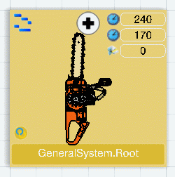
The icon in the top left corner represents the system type (for example, General System). The name of the system is displayed at the bottom of the tile.
If a scope is defined between the system and a process, an icon ![]() appears in the bottom left
corner.
appears in the bottom left
corner.
Expand/Collapse Icon
The Expand icon ![]() at the top center indicates that the system has children. You can click on this icon to see the child systems inside a "frame" representation of the father system.
at the top center indicates that the system has children. You can click on this icon to see the child systems inside a "frame" representation of the father system.
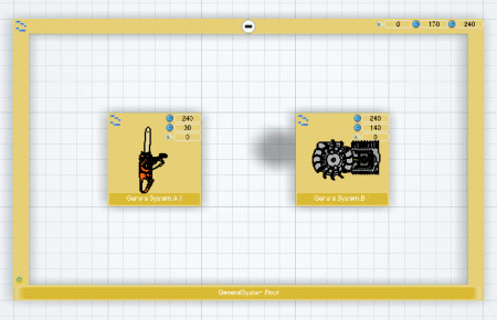
The Collapse icon ![]() on the frame allows you to go back to the tile representation again.
on the frame allows you to go back to the tile representation again.
Numerical Values
The following information is displayed
in the top right corner of the tile:
- Current Cycle Time, which is the cycle time of the root system
- Total Time of Operations, which is the sum of the durations of all the operations under the system
- Number of Assigned Fasteners, which is the number of fasteners assigned to the system (or to child systems of the system).
You can choose to show or hide this information (see System Editor tab in Tools > Options > Manufacturing Planning).
Visual Feedback on Tiles with No 3D Representation
If there is no 3D representation of the assigned parts on a system tile, process icons are displayed on the system tile.
If the system has a scope with a process, an icon representing the process with a scope link to the system is displayed in transparent mode. A process is identified by means of a tooltip.
![]()
All processes linked to operations within the system are taken into account. When there are several possible processes only the last processes are shown. For example, if there is a data requirement between P1 to P2 and both processes are implemented, then only P2 is shown. The icons have a non-transparent visualization.
![]()
A maximum of four icons can be shown. If there are more than four processes, a symbolic forth icon "groups" the remaining processes, which are identified by means of a tooltip.
![]()
Customized Picture on System Tile
You can set a customized picture for a system reference object by valuating the Picture Name attribute in the system's Properties dialog box.
\intel_a\resources\graphic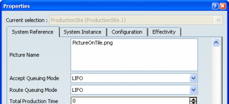
The image file must be located in the \intel_a\resources\graphic folder. The allowed image formats are jpg, png and bmp
A example of such an image on a system tile is shown below:
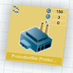
![]()
PLM Compass
The East Quadrant of the PLM Compass allows you to obtain the assignment status of processes on the current system level. It also allows you to analyze implements links of any kind of entity (Product, Process, Resource, System or Operation) to determine which entities are linked to it.
The PLM Compass is located in the main or maximized frame. All Compass actions that actively modify the viewer do not work in other viewers at the same time.
Process Assignment Status
When you activate the East Quadrant of the PLM Compass, the assignment
status of processes is displayed. 
The color code depends several factors:
- Assignment status of the process
- Visibility of the process from a system: a process is visible from the system if it can be realized by an operation of the system. The visibility can be delimited by a scope.
- For an Assemble process with a scope, color depends on possible alternative to the assignment.
Colored squares are displayed in the tree in front of each process node to give appropriate information according to the following legend:
- Fully assigned Processes: In some cases, an Assemble process can be assigned as both a Provide process and an Assemble process. A fully assigned process reflects a state where, for example, an Assemble process (with a scope) is already assigned as both a Provide and an Assemble in the current system.
- Assignable Processes: Processes that are not yet assigned, but which can be assigned (taking into account assignment rules and System-Process scope).
- Assigned Processes: Processes that are assigned in the current system.
- Assigned more than once Processes: Processes that are realized by at least two operations. This is possible, for example, if a processes is realized by operations in different configurations.
- Non-assignable Processes: Processes cannot be assigned because this would lead to a violation of assignment or scope encapsulation rules.
- Half-assigned Processes: In some cases, an Assemble process can be assigned as a Provide process and an Assemble process. A half-assigned process reflects a state where, for example, an Assemble process is already assigned as an Assemble and is still assignable as a Provide in the current system.
For more information, see Using PLM Compass for Process Assignment Status.
Implement Link Analysis
You can use the arrow next to Process Assignment Status to view a drop-down list that allows you access to Implement Link Analysis.

For any kind of entity (Product, Process, Resource, System or Operation), it is possible to determine which entities are linked to it. Different colors are applied to the various entities in the tree and, possibly, depending on the analysis.
For more information, see PPR Navigator User's Guide > About the East Quadrant of the Compass.
System Update Status
You can use the arrow next to Process Assignment Status to view a drop-down list that allows you access to System Update Status.

The System tiles and tree nodes are highlighted according to the following color code:
- Green: the implemented link of the system and the implement links all the system's children point to processes loaded in the session
- Red: the System-Process scope link is broken: the process is deleted from the database or is not loaded
- Yellow: the implemented link one of the system’s children is broken: the process is deleted from the database or is not loaded.
![]()
How to Select Parts/Assemblies
A number of capabilities are available for selecting parts and assemblies from the 3D representation (for example, in order to Drag and Drop).
Smart Zoom Capability
The Smart Zoom capability is useful to investigate the 3D representation and for better selection handling. The tile is zoomed until the 3D representation "takes off". The 3D representation can be rotated and zoomed.
![]()
Note that the Smart Zoom capability is deactivated by default. See Live Editors tab in Tools > Options > Manufacturing Planning. However, it can be activated at any time by means of the F6 key.
Digger Functionality
The Digger functionality is available when the Smart Zoom is active. It is used to temporarily disable geometry that hides other parts of 3D. Move the mouse cursor onto the outer geometry and press the F7 key. The hiding geometry becomes transparent and the hidden geometry can then be selected or made transparent. Use the F8 key to make geometry visible again.
See Navigating within the Process Editor > Using Digger in the Process Definition User's Guide.
![]()
How to Assign a Process to an Operation Under a System
To assign a process to an operation, the process can be dragged from Live Process Editor onto a system tile. It is also possible to drag the process from PPR tree, if it is activated in the main frame.
You can also use Assign
Processes to Operation ![]() and then select processes in the dialog box that appears. SeeManaging Process to Operation Assignments.
and then select processes in the dialog box that appears. SeeManaging Process to Operation Assignments.
The system tile does not show any indication of implemented processes until the processes have parts assigned. The implemented processes can be displayed in an F5 list by pressing the F5 key. See Use F5 List to Show Assigned Data.
When systems implement processes that have parts with 3D information, the parts are shown on top of the system tiles.
The 3D representation of all parts/assemblies that enter the system and all parts that are assembled by the system are displayed. Note that if a process output is defined on a process it is not taken into account.
Parts that are displayed on top of system tiles can also be dragged directly from these systems to other systems.
![]()
How to Change System Levels
The Live System Editor displays only systems of a single level of hierarchy at any given time. There are a number of capabilities for changing system level such as thumbnail view and the Up/Down icons in Smart Zoom.
Thumbnail View
The thumbnail view on the left side of Live System Editor shows the parent levels. Click one of these thumbnails to change to the respective level.
![]()
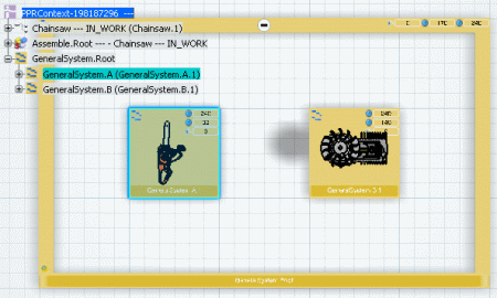
Cross-highlighting between Live System Editor and PPR Tree
The cross-highlighting capability allows objects to be highlighted in both the Live System Editor and PPR tree.
For example, to highlight a system in the Live System Editor, click that system in the PPR tree.
Similarly, to highlight a system in the PPR tree, click that system in the Live System Editor.
![]()
Drag and Drop Capabilities
A number of drag and drop capabilities are available in the Live System Editor itself and also between the Live Process Editor and the Live System Editor.
Move Operation by Drag and Drop in Live System Editor
Selecting a 3D representation implies selecting the operation linked to a Provide process which in turn is linked to the concerned part. By moving an operation, all linked Provide processes and parts are also moved to the target system.
You can drag and drop a 3D representation from an existing system to another existing system. In this case, the instance of operation under the source system is deleted and the reference of the operation is instantiated under the target system.
Note that it is not possible to move an operation by drag and drop onto an empty tile of the LSE grid.
Drag and Drop between Live Process Editor and Live System Editor
When a process tile is dragged from the LPE and dropped on an empty tile in the LSE grid :
- A General system is created
- A General operation is created in the General system. This operation is assigned to the dragged process.
When a 3D representation is dragged from LPE and dropped on an empty tile in LSE grid:
- A General system is created
- A Loading or Point Fastening operation is created into the General System. This operation is assigned to the Provide process which is linked to the part corresponding to the 3D representation.
When a 3D representation is dragged from LPE and dropped on an existing system in LSE:
- A Loading or Point Fastening operation is created in the General system. This operation is assigned to the Provide process which is linked to the part corresponding to the 3D representation.
When a process tile is dragged from LPE and dropped on an existing system in LSE:
- A General operation is created in the General system. The operation is assigned to the dragged process.
When an Assemble process from LPE is dragged and dropped in LSE on a system which has a defined scope with the same Assemble process, the same context applies. In this case, a General operation is created under the system.
If the Automatic creation of loading and point fastening operations option is selected in the System Editor tab of the Tools > Options > Manufacturing Planning, all Provide and Fasten processes that are linked to the Assemble process are also assigned.
Automatic Creation of Operations by Drag and Drop of an Assemble Process
When the Automatic creation of loading and point fastening operations option is selected in the System Editor tab of the Tools > Options > Manufacturing Planning, the following capabilities are available.
Drag and drop an Assemble process from LPE on an empty tile in LSE:
- A General system is created
- A General operation is created in the General system
- The General operation is assigned to the Assemble process
- Several Loading and Point Fastening operations are created. These operations are assigned to the Provide and Fasten processes linked to the Assemble process.
Drag and drop an Assemble process from LPE on an existing tile in LSE:
- A General operation is created in the General system
- The General operation is assigned to the dragged process
- Several Loading and Point Fastening operations are created. These operations are assigned to the Provide and Fasten processes linked to the Assemble process.
At the first drag and drop of an Assemble process in the Live System Editor, all Provide and Fasten processes linked to the Assemble process are assigned. For any subsequent drag and drop of that same Assemble process, only the Assemble process is assigned.