Open Live System Editor
When you start the Manufacturing System Definition workbench, the Live System Editor appears in the main frame.
- Select Start
 > Manufacturing Planning > Manufacturing System Definition.
The Live System Editor appears in the main frame. It is easily identified by its characteristic grid.
Only the root System reference is created: no automatic
creation of a System is done. The displayed grid can be considered as
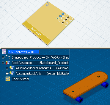
the child level of the root System reference. Here is a typical view of the Live System Editor in the top frame and the 3D view in the bottom frame.
Note that there is no automatic link created between
the root System reference and the root Process reference.
When you leave the Manufacturing System Definition workbench, it is replaced
with the default editor content of the target workbench.

Switch between Different Frames
You can switch the lower frame of the Live System Editor to the PPR tree view.
This is useful for working on the complete Product and Resource data
that is not structured in a manufacturing view (design positions).
Make sure that the Live System Editor
 is selected in the Views toolbar. is selected in the Views toolbar.
Only the Live System Editor is displayed on the screen (that is, it is the only frame visible on the screen). Click Live System Editor and 3D View
 in the Views toolbar. in the Views toolbar.
The PPR tree appears in the frame below the Live System Editor.
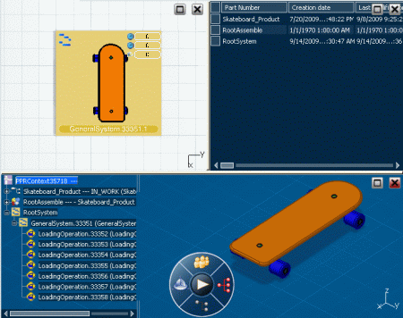
The following image shows the 3D view in the lower frame, the Live
System Editor in upper left frame, and Sheet Editor in upper right frame.
The Maximize  button
brings the selected frame to single-frame view. From a maximized view, it is possible to switch to another user activity. button
brings the selected frame to single-frame view. From a maximized view, it is possible to switch to another user activity.
The Close  button closes the selected frame: a three-frame layout becomes two frames,
and so on. It is only available for the top frames.

Create Systems in Live System Editor
When you start the Manufacturing System Definition workbench and open the Live System Editor,
a PPR Context object and a root System
are created. You can then create systems using the balloon toolbar that appears on the LSE grid, for example.
If Manufacturing System Definition is started by changing from another
workbench, no PPR Context object is created: the existing one is used. If
there are already Systems below this PPR Context, no new Systems are created
and Live System Editor displays the existing root System.
To create a new System, double-click on the grid.
The new System tile must be at least one tile away from
any other tile.
A balloon toolbar appears for creating a new General system or inserting an existing System from database.
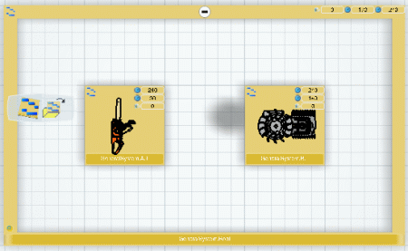
Click Insert General System  in the balloon toolbar. in the balloon toolbar.
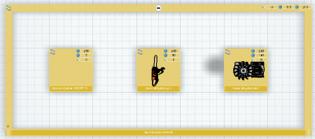
A new System tile is created on the grid for the new General system.
Note:
For more information, see Defining Systems.

Edit System Properties
You can edit the reference, instance, configuration and effectivity attributes of a system in the Properties dialog box.
Right-click the System in the Live System Editor and
select Properties.
The Properties dialog box appears.
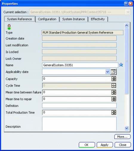
Make the desired modifications to the System properties
and click OK.

Delete a System
You can delete a system using the contextual Delete command.
Right-click the system that you wish to delete. Click Delete.
Note:
- You can click Undo
 to recover the system. You may need to refresh the view by clicking Refresh Live System Editor to recover the system. You may need to refresh the view by clicking Refresh Live System Editor  . .
- The root system reference cannot be deleted.

Create Product Flow Links
You can create product flow links between systems using the Create a Product Flow command.
Click Create a Product Flow  . . Select the System tile corresponding to the source system.
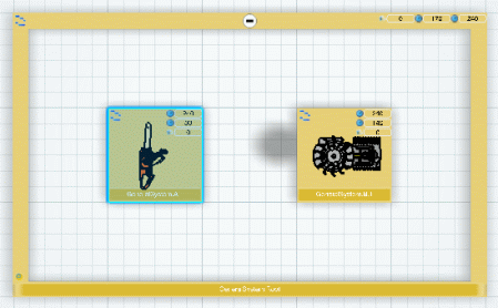
Select the System tile corresponding to the target system.
The product flow is created between the two Systems.
This is symbolized by a blue arrow linking the two System tiles.
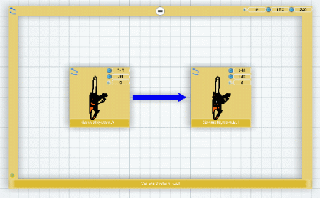
When defining a product flow between two systems, both systems must
be under the same father. However, they can be at different levels in
the hierarchy of systems.
A product flow is "from" one system only and "to" one system only.
But there can be several flows from one system or several flows to one
system.
To delete a product flow, click on the arrow linking the two System
tiles then press the Delete key. Alternatively, right-click the arrow
and select Delete.

Use Visualization Modes
You can manage the display of the 3D representation on the System tile by the options in the
Live System Editor Visualization Modes toolbar. The 3D view on the tile is the result of the processes realized on the system. You can filter this view using the available options.
Click Show All Parts  . .
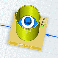
All parts are visible.
Click Show Only Concerned Parts  . .
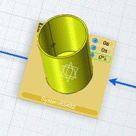
Only the parts concerned are visible.
Click Show Unconcerned Parts as Transparent  . .
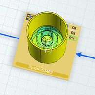
Only the parts concerned are visible, the other parts are transparent.

Assign/Unassign Processes Using Live Process Editor
You can drag and drop processes from the Live Process Editor to assign them to systems in the Live System Editor. By doing this, you may create operations on the target systems.
In the Live Process Editor, under the root process create an Assemble process with Provide processes. Switch to the Live System Editor, and create two systems. Create a scope between the root Process and root System. Switch back to the Live Process Editor.
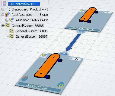
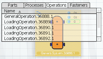
Position the Live Process Editor and the Live System Editor in the top and bottom frames of the screen. Drag and drop the Assemble process tile from the Live Process Editor to the first System tile in the Live System Editor. The Assemble process is assigned to the system. Note that several operations are created.
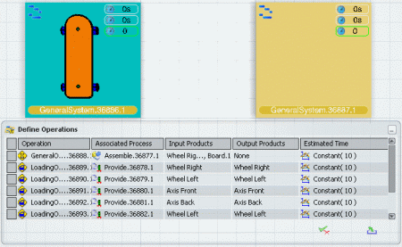
These operations can also be seen in the F5 list:
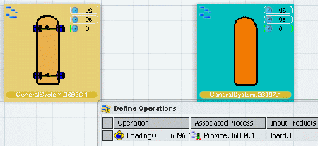
Drag and drop a part (for example, the board) from the Live Process Editor to the second System tile in the Live System Editor. The corresponding Provide process is now assigned to the system. Note that a Loading operation is created.
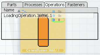
This operation can also be seen in the F5 list:
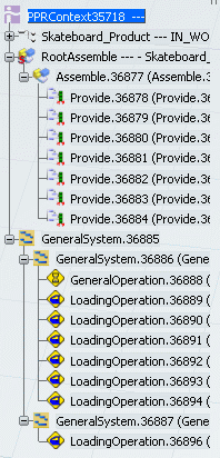
The result can be seen in the PPR tree.

Show Assigned Data Using the F5 List
You can list information about the system's assigned parts, processes, operations and fasteners by pressing the F5 key.
Press F5 on the keyboard to display assigned
data (Parts/assemblies, Processes, Operations and Fasteners) in an F5
list.
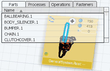
The Parts tab is selected by default. Clicking on any part in the list highlights the corresponding part in the 3D representation on the tile.
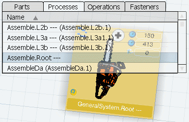
Select the Processes tab to list the processes implemented within the system. The process that has a scope link with the system is highlighted with a dark background.
Note:
The Live Process Editor has a similar F5 list. You can drag and drop a process from the F5 list of the Live Process Editor to
the Live System Editor.
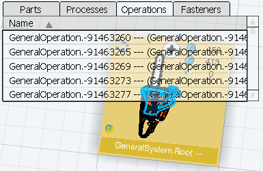
Select the Operations tab to list the operations contained in the system. Clicking on any operation in the list highlights the corresponding part in the 3D representation on the tile.
You can use the Manufacturing System Gantt for displaying
the operations owned or executed by a System.
|
 > Manufacturing Planning > Manufacturing System Definition.

![]()

 button
brings the selected frame to single-frame view. From a maximized view, it is possible to switch to another user activity.
 button closes the selected frame: a three-frame layout becomes two frames,
and so on. It is only available for the top frames.
button closes the selected frame: a three-frame layout becomes two frames,
and so on. It is only available for the top frames.![]()
![]()
![]()
![]()


