Working with Callouts | |||
| |||
Create Callouts in Reference View
You can create callouts for section views, section cuts (including multi-plane section views/cuts) or auxiliary views, in other reference views using the Create Callout in Reference View command. This command is available if at least a single layout view supports callout addition.
Select a suitable view for callout creation. For more information on suitable views, refer to About View Callouts.
The callout is created in the selected view.
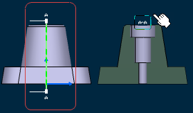
Note: The callout is automatically relimited on the 3D background of the view in which it is placed.
![]()
Position Callout Texts Manually
You can position the callout texts freely anywhere using the Position Texts Manually command. This command is available on the contextual menu of callout texts and callout representation.
| Tip: The contextual menu is accessible when the pointer is over callout representation or callout texts. |
Right-click the callout text and select Position Texts Manually.
An outlined box with a solid line type is displayed on the selected callout texts. This indicates that the callout text is in manual positioning mode. It is now possible to move the callout text anywhere by dragging it.
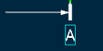
Drag the selected callout text and drop it to the required position in the graphic area.

Notes:
- You can multi-select the callout texts. However, in this case, only the callout text which is directly picked and dragged is moved; other callout texts (or annotations) involved in the selection are not considered.
- If you clear the Position Texts Manually contextual command, then the callout texts' position is restored to the previously set standard position.
![]()
Edit Callouts
You can edit a callout by double-clicking on the callout representation or executing the Definition command from its contextual menu.
Notes:
- You can only edit the projection or section callouts by modifying the location of callout extremities. However, you cannot edit the multi-plane section callouts. Because, such callouts are created from a 2D profile and their extent is explicitly specified through this 2D profile.
- You cannot edit a callout text's string, as its purpose is to reflect the resulting view identifier.
Double-click the callout.
Two white square manipulators appear. You can modify callout extremities location by moving these manipulators.
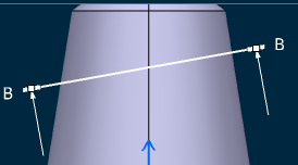
Drag the manipulators and drop them to the required position in the graphic area.
Tip: Press the Ctrl key to move the second callout extremity simultaneously. In this case, the second callout extremity moves in the opposite direction. Important: - You can move the extremities only along the callout's support. However, you cannot modify the callout's support itself, as it's just a representation of a view's specifications.
- You cannot move a callout extremity beyond the other extremity. In this case, the other extremity also moves (both extremities are coincident).
Notes:
- When the callout is in edition mode and the Position Texts Manually contextual command is selected, you can position the callout texts freely.
- When the callout is in edition mode and the Position Texts Manually contextual command is not selected, the pointer representation changes to
 .
.