Click Profile
 in the
Geometry Creation toolbar.
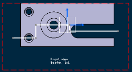
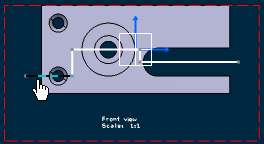
Draw a multiple segment profile.

Click New Section/Auxiliary View
 in the Layout toolbar (Views sub-toolbar).
Select the first line of the multi-segment profile.

The Tools Palette toolbar is automatically displayed
with the following options:
-
 Auxiliary View: Creates an auxiliary view.
-
 Section View: Creates a section view.
-
 Section Cut: Creates a section cut.
-
 Create Datum: This option
is not available.
Click Section View
 or Section Cut
  .
.
Click on the sheet at the location where you want the section
view to be positioned.
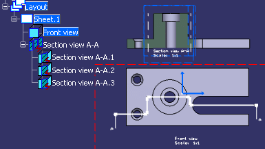
The multi-plane section view is created and is represented in the specification
tree along with its sub-views as children nodes. The corresponding callout
is automatically created in the current view identical to the profile. The
sub-views share the same origin in the layout sheet, and their local axes
(H and V) overlap.
If you selected Section View, the result is as shown below:

Note:
The multi-plane
section view is not linked to the profile view. You can position it independently
anywhere in the sheet.