In the 2D window, click New View From
 in the Layout toolbar (Views sub-toolbar).
The Tools Palette toolbar appears. You will not need it for this scenario. Perform either of the following operations: - Select the FTA multi-plane section view.

- Select the FTA capture associated to a multi-plane section view.

The Tools Palette toolbar automatically disappears, as the
views are considered to be fully defined by their reference FTA multi-plane
section views in naming, type, orientation and scaling.
A preview of the created 2DL multi-plane section view is displayed under
the pointer and moves along with it.
Click on the sheet at the location where you want the view
to be positioned. In case you have selected several multi-plane section views,
click in the sheet as many times as necessary to position all the 2D Layout
views.
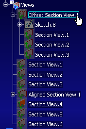
The multi-plane section view is created and is represented in the specification
tree along with its sub-views as children nodes. Optional: If a message box is displayed, prompting you to confirm the creation of a callout, click OK and select a suitable view for callout creation. For more information, refer to About View Callouts.
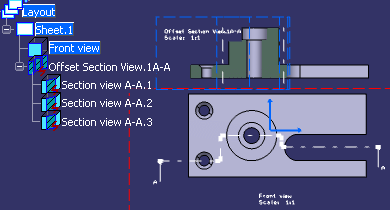
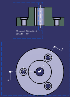
The multi-plane view is created along with its callout.
- If you selected the FTA multi-plane section view:

- If you selected the FTA capture associated to a multi-plane section view:

Notes:
- When selecting a capture, FTA annotations are added in sub-view's filters. Furthermore, the FTA annotation set is added in the section view's filter (it is therefore invisible in the clipped background).
- When selecting an FTA view, by default, annotations are not displayed. You need to add them manually in the sub-view's filters.
|


