About Use-Edges | ||
| ||
What Are Use-Edges?
This sub-topic explains what use-edges are.
Use-edges are key in a concurrent engineering process, helping you with your design by letting you re-use existing elements from a 3D shape coming from another designer for example. In other words, use-edges help you create geometry from existing 3D shapes as well as from other layouts.
The 2D Layout for 3D Design workbench provides the following use-edge functionality:
- Projecting 3D Elements onto the View Plane: lets you create geometry in the current design view by projecting a 3D element onto the view plane.
- Intersecting 3D Elements with the View Plane: lets you create geometry in the current design view by intersecting a 3D element with the view plane.
- Projecting 3D Silhouette Edges: lets you create geometry in the current design view by projecting the silhouette edge of a 3D element onto the view plane.
- Creating Associative Use-Edges: lets you create use-edges of the above types that will be associative to the reference geometry.
- Offsetting 3D Elements Associatively: lets you create offset use-edges that will be associative to 3D elements (surfaces or edges).
- Deleting Useless Elements: lets you identify and delete useless use-edge input elements from the active layout in one shot.
![]()
What You Need to Know About Use-Edges
This sub-topic provides essential information about use-edges.
Use-edge commands are available only in a 3D shape layout. As no geometry creation is allowed in the case of a product layout, they are not available in this context.
Moreover, use-edge commands are only available when the current view is a design view. In other words, they are not available in isometric views (because they are not design views).
The input element (the element to be projected or intersected) is any visible geometry which does not directly belong to the current view. This means that you can select geometrical elements contained in the 2D or 3D background of any view, as well as geometrical elements contained in non-current design views, with the exception of geometry in a 2D component instance which cannot be selected.
The table below sums up the types of elements that you can select, depending on where they are located and visualized.
| Can I select geometry in... | ...is it visualized in the current view? | ...is it visualized in other views? |
|---|---|---|
| ...the 3D background... | Yes | Yes |
| ...the 2D background (except 2D Component instances)... | Yes (except geometry defined in the main view) | Yes, (except geometry defined in the current view) |
| ...a design view (except 2D Component instances)... | No | Yes |
As shown in the table above, you can select geometry which is not only visible in the current view, but also in a different view.
![]()
Differences with Use-Edges in Sketcher
This sub-topic explains the differences between use-edges in Sketcher and use-edges in 2D Layout for 3D Design.
If you are familiar with the Sketcher workbench, you need to be aware that use-edges in 2D Layout for 3D Design differ from use-edges in Sketcher to a certain extent.
Indeed, by default, use-edges in 2D Layout for 3D Design are not created associative with their reference element. In this case:
- any modification of the reference geometry is not reflected in the use-edge, even after an update operation.
- use-edge elements are simply datum elements (Point, Line, Circle and so on).
- non-associative use-edges are not visualized in the specification tree.
![]()
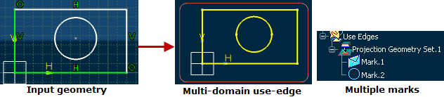
About Multi-Domain Use-Edges
You can create multi-domain use edges (silhouette, intersections, projections) with multiple domains in geometrical result.
Multi-domain use-edges are composed of multiple marks. Therefore, any modification done on the geometrical input specification is reflected on mark geometries. As a result, during update, marks can be created, deleted or modified.
During update, use-edges are modified according to their geometrical input specifications and use-edge marks are also modified to match those changes.
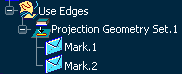
Consider the following case of multi-domain use-edge displaying multiple marks:
The following table describes the geometrical modifications done on this use-edge and their effect on mark geometries:
| Geometrical Modification | Use-edge after Update | Marks after Update | Result |
|---|---|---|---|
| Domain associated to mark is removed. | 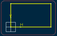 |
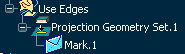 |
Constraints relying on the mark are destroyed and the associated mark is removed. |
| Domain is merged into another domain. | 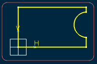 |
 |
Marks corresponding to merged domains are not destroyed, but both are associated to the whole merged domain. |
| Domain is modified and a new domain is created. | 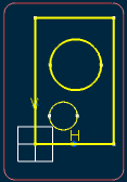 |
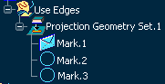 |
When domain is modified, each mark associated to previous domain is transformed to match the new geometrical result of this domain. When a new domain is created, a new mark is created, and is associated to this domain. |
Note: While creating a use-edge using the Project 3D Elements command, you can select a sketch or a face of 3D shape and directly create one or many marks instead of selecting edge by edge.
![]()
When Use-Edges Are Associative
This topic provides information about associative use-edges.
-
Associative use-edge marks are used as other 2D curves
to create dimensions, constraints or annotations. You can create dimensions
for a mark or for a mark sub-element as for any other 2D geometry.
- If a mark is composed of a single element, you can create dimensions, annotations and constraints for it.
- If a mark is composed of multiple elements, then you can only create dimensions and annotations for its basic sub-elements. You cannot create dimensions for the whole mark.
-
Use-edges are visualized in yellow color with thickness
and linetype as defined in the current curve standards, which is modifiable
in the Style toolbar.
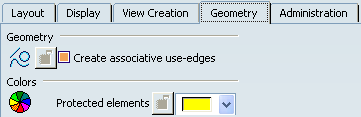
The color can be modified globally for the next created use-edges using
Tools > Options > 2D Layout for 3D Design > Geometry tab,
Colors area, Protected elements list.
- When the input geometry of a use-edge or the plane support of the 2D Layout view changes, the use-edge mark becomes not up-to-date. When a mark is not up-to-date, the update icon appears in the specification tree, on the icon of the view which contains this mark. You cannot update a use-edge independently of the view which contains it.
- If the geometry undergoes a major change (such as deleting the edge of a solid) which prevents the use-edge from being updated, then an error related to this use-edge is triggered when updating the view.
- When a use-edge is deactivated, then it is not updated even if the input geometry or the view plane changes. Activating or deactivating a use-edge mark will activate or deactivate all marks for that use-edge.
- When deleting a use-edge mark, the whole use-edge is deleted.
- Use-edges which have geometry imported from other 3D shapes as an external reference or a datum geometry, will not be deleted when the use-edges are deleted. You must delete these imports specifically if you do not need them anymore.
- You can isolate a use-edge using the contextual menu available on each mark. When isolating a use-edge mark, this use-edge and its marks are deleted and replaced by identical standard 2D geometries, with no link to the input geometrical element. Dimensions and annotations created on this use-edge marks are not automatically rerouted to new isolated geometries. The Isolate command is also available using the Use-edges tab of the Sketch Analysis dialog box using the Tools > Sketch Analysis command.
- When creating a new 3D shape in the Product Data Filtering workbench, the use-edges in the new 3D shape are isolated.
-
The command
can be launched for associative use-edges of the following types:
- Projection
- Intersection
- Silhouette
- Mark
- Associative use-edge inputs are listed in the specification tree after the sheets node.
- You can delete use-edge inputs from the specification tree. When you delete a use-edge input, all use-edges impacted by this input will be marked as not up-to-date. You will have to edit, deactivate, isolate or delete these use-edges.
- If a use-edge is made up of multiple connex geometries, then associativity with the geometrical input is not kept. A message informs you when this is the case.
- Annotations created on a sub-element mark cannot be moved to another sub-element mark.
- Center lines and axis lines cannot be created on use-edge sub-elements.
- Use-edges are not created automatically when offsetting or constraining elements.
- Mark sub-elements are not accessible when they are seen in the 2D background of a view. Thus, you cannot add a dimension on a sub-element of a 2D mark if it does not belong to the edited 2D layout.
- Use-edges can be analyzed in the Sketch Analysis command, in the Use-edges tab of Sketch Analysis dialog box. For more information, refer to Analyzing View Geometries.
- You can create a driving dimension between a simple use-edge and a geometrical element. In this case, if the use-edge is isolated, the driving dimension takes into account the geometrical element created from the isolated use-edge.
- When designing at the Physical level, in the RFLP Navigator: If the option Keep link with selected object is selected in , you can only create associative use-edges with edges that are in the same product as the 3D shape representation containing the 2D layout. If you select an edge that is in another product, an error message appears, informing you that the selected elements cannot be projected.
![]()
Input Geometries for Associative Use-Edges
This topic provides information about input geometries for associative use-edges.
Geometrical inputs of a use-edge can be located in the same 3D shape representation than the 2D layout representation, or in an external representation. The following types of geometries can be provided as inputs:
| Use-edge functionality | 2D Geometries | 2D Use-edges | Vertices | Edges | Faces | Volumes | Bodies |
|---|---|---|---|---|---|---|---|
| Projection | Yes | No | Yes | Yes | Yes | Yes | No |
| Intersection | Yes | No | Yes | Yes | Yes | Yes | Yes |
| Silhouette | No | No | No | No | Yes | Yes | Yes |
| Offset | Yes | No | No | Yes | Yes | Yes | No |
Note: You can also select faces and features in the specification tree as an input for the silhouette use-edge.
When creating a use-edge from a geometrical input external to the 3D shape containing the edited 2D layout, a geometrical import will be created in the current 3D shape. Whether this geometrical is linked to the original geometry depends on the option Keep link with selected object, in Tools > Options > Infrastructure > 3D shape Infrastructure > General tab.
Associative use-edges are the use-edges which are associative to the geometrical inputs. If input geometry is modified, then the use-edge becomes not up-to-date, and can be updated using the view update. To create associative use-edges, select the option Create associative use-edges, from the Tools > Options > 2D Layout for 3D Design > Geometry tab. If this option is cleared, then non-associative use-edges are created. The associative use-edge created on input geometry is composed of one or several marks, that define one or more connex areas of the geometry. The marks created can be simple or complex curves. Simple mark consists of single basic 2D element and complex mark consists of multiple 2D elements.