Splitting and Trimming Geometry (common options) | |||||
|
| ||||
Keep and Remove Elements
The
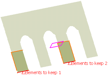
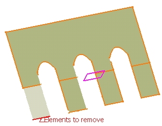
Elements to remove and Elements to keep options allow to define the portions to be removed or kept when performing the split operation.

![]()
Compute Intersections
You can compute the intersection of the surfaces by selecting Intersections computation check box.
This option is not selected by default.
- Select the Intersections computation check box to create
an aggregated intersection when performing the trimming operation.
This element will be added to the specification tree as
Intersect.xxx.
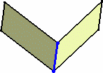
Warning: In case there are several elements to cut, the Intersections computation option only applies on the first selected element.
![]()
Extrapolate
You can extrapolate the cutting curve or surface.
This option is selected by default.
- Clear Automatic extrapolation if do not you want the automatic
extrapolation of the cutting curve.
When a splitting curve is extrapolated, the extrapolation will performed on the original curve, providing the underlying geometry (that is the curve) is long enough to be used for the extrapolation.
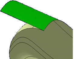
If Automatic extrapolation is cleared, an error message is issued when the cutting element needs to be extrapolated, and the latter is highlighted in red in the 3D geometry.
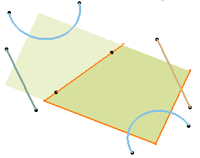
Important: For the Split command, this option is available in the case of a split surface/curve or surface/surface.
For the Trim command, if the Automatic extrapolation option is cleared, an
error message is issued when the elements to trim need to be
extrapolated, and the latter are highlighted in red in the 3D
geometry.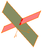
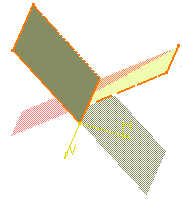
To be able to trim the two surfaces or wireframe elements, select the Automatic extrapolation option.
![]()
Select a Support
When splitting or trimming wires (curve, line, sketch and so forth) by another wire, you can select a support to define the area that will be kept after splitting or trimming the element.
It is defined by the vectorial product of the normal to the support and the tangent to the splitting or trimming element.
This is especially recommended when splitting or trimming a closed wire. In our example, the sketch composed of two lines is trimmed by the circle.
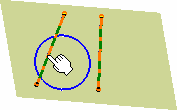
- Select a support.
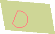
Here is the result when no support is selected:
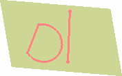
![]()
Split/Trim Closed Surfaces by Two Connex Surfaces or Curves
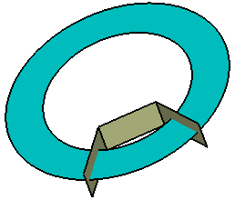
When splitting a closed surface or a curve by connex elements, an error message is issued. You need to create a join feature of non connex elements and cut the closed surface or curve with this join feature.
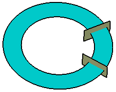
![]()
Split/Trim a Surface when Elements are Tangent to Each Other
Splitting a surface by another surface one requires the computation of the surface intersection. When the surfaces to be intersected are tangent, there are ways to avoid intersections.
Whenever possible, intersections and input elements that are tangent to each other should be avoided.
Similarly, the following cases should be avoided when possible (especially when the tangency constraint between the two surfaces has not been clearly defined by the user during the surface creation), as the result of the positioning is likely to be indeterminate and the result of the intersection to be unstable in the tangency zone.
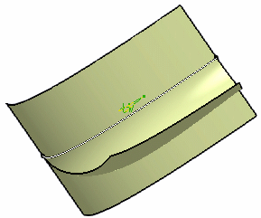
Here is an example of tangent surfaces: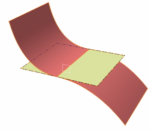
![]()
Split/Trim a surface when surfaces are tangent or intersect face edges
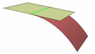
You can use the border edge of the cutting surface to split the element to cut or trim the element.
![]()
Split/Trim Non-Intersecting Elements
You can split/trim non-intersecting elements by projecting the points on the surface to be cut.
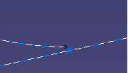
In the example below, the distance between the circle and the line is greater than the resolution but less than 0.01mm. There is a way to split/trim the line and obtain a result with no gap.

