Defining a User-defined Connection Property | ||||||||
|
| |||||||
When needed, click
 to define the parameters.
The corresponding dialog box appears. The order of the parameters displayed in the dialog box depends on the element type you selected.
- If your selection contains a contact element, enter a clearance value.
- If your selection contains a spring element, choose the axis system (see Modifying the Axis System), enter the values for translational and rotational stiffness components of the spring.
- If your selection contains a beam element, define 1D property parameters. See Finite Element Modeling User's Guide: Creating Structural Properties: Creating 1D Properties.
Important: The availability of some of the beam parameters depends on your available licenses. See Licensing. - If your selection contains a bolt element, enter a value of tightening force.
In the Connected Geometries area, click
 to select the geometries that are physically in contact.
The Connected Geometries dialog box appears. For more details about the supports you can select, see Supports for a User-defined Connection Property.
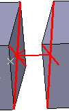
A user-defined connection property is symbolized as shown below: