Creating an Engineering Connection | |||
| |||
Click Engineering Connection
 .
.
The Engineering Connection Definition dialog box appears.
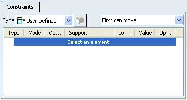
Important: The Engineering Connection Assistant toolbar appears.
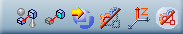
These options help you to select/show relevant or irrelevant components to a regular engineering connection, to use constraints in an engineering connection in order to position components.
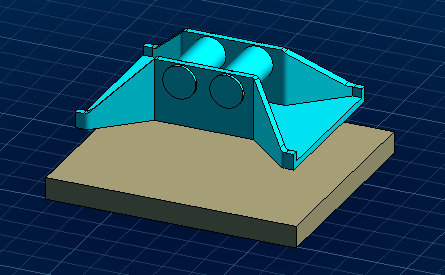
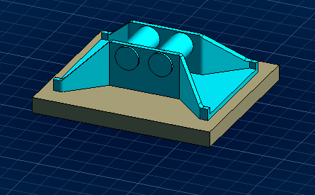
The assembly looks like this.
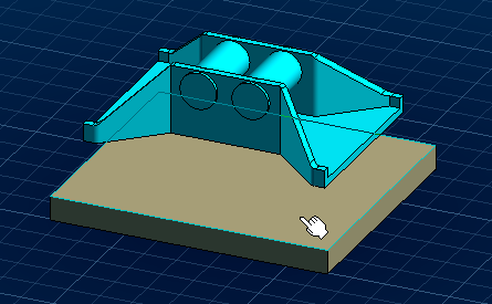
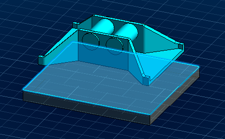
Select the face as shown on Jack_Pad.1.
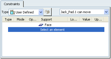
The Engineering Connection Definition dialog box is updated:
- The first selected element is recognized as a plane in the support list.
- Jack_Pad.1 is the element which will be repositioned during the PLM update.
The selected element is highlighted and the 3D shape is displayed in transparency.
Important: Because the Shade Affected option is on
 the 3D shape is displayed with shading.
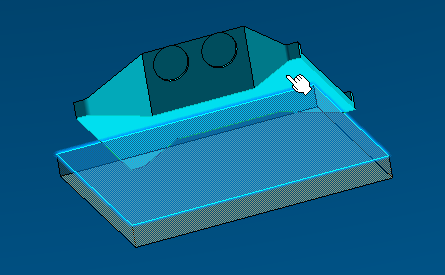
Select the face as shown on Jack_Frame.1.
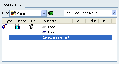
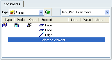
The Engineering Connection Definition dialog box is updated:
- The second selected element is recognized as a plane in the support list.
- The created constraint is
Contact
 by default, according to the selected elements.
 - The engineering type is deducted from degrees of freedom in the engineering connection, here: Planar
 .
.
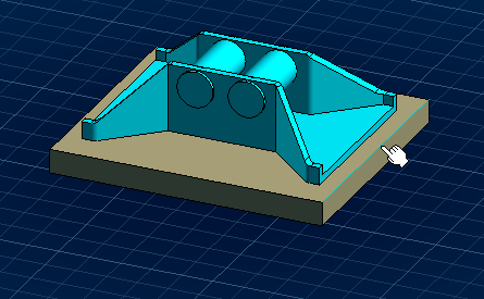
The constraint is applied and Jack_Pad.1 has been repositioned during the PLM update according to the engineering connection orientation.
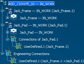
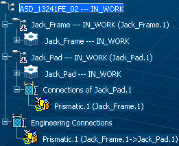
The engineering connection is created in the specification tree:
- Under the active product: ASD_13241FE_02.
- Under the Jack_Pad.1, the element which can be repositioned during the PLM update according to the engineering connection orientation.
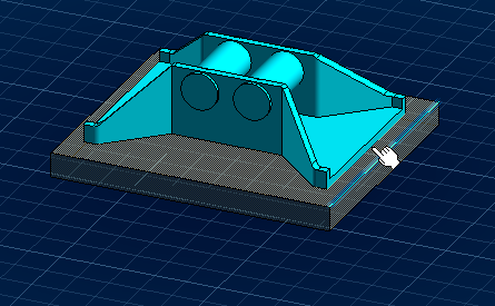
Select the line as shown on Jack_Pad.1.
The Engineering Connection Definition dialog box is updated: the first selected element is recognized as a line in the support list.
Select the line as shown on Jack_Frame.1.
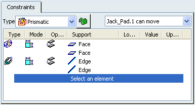
The Engineering Connection Definition dialog box is updated:
- The second selected element is recognized as a line in the support list.
- The created constraint type is
Coincidence
 by default, according to the selected elements.
- The engineering type is deducted from degrees of freedom in the engineering connection, here: Prismatic
 .
.
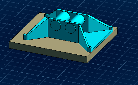
The constraint is applied and Jack_Pad.1 has been repositioned during the PLM update according to the engineering connection orientation.
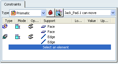
Click Lock/Unlock Engineering connection type
 .
.
The Engineering Connection Definition dialog box is updated:
- The engineering type is locked
 .
.
- The created constraint type is
Coincidence
by default, according to the selected elements.
- The engineering type is deducted from degrees of freedom in the engineering connection, here: Prismatic
.
The engineering connection name and icon are updated in the specification tree.
- The engineering type is locked
Click OK in the Engineering Connection Definition dialog box.
The Prismatic.1 engineering connection is created.
Important: While the Positioning Mode option is on
 , no engineering connection is created although you click
OK in the
Engineering Connection Definition dialog
box.
, no engineering connection is created although you click
OK in the
Engineering Connection Definition dialog
box.