Modify the Axis System in a Preprocessing Specification Context
You can modify the axis system of preprocessing specifications (loads, restraints, 3D properties, connection
properties).
When you create a preprocessing specification in a simulation,
you can choose the axis system and the coordinate system you want to use
to define the components of the preprocessing specification. The type of axis system you
can choose depends on the preprocessing specification you create.
To modify the axis
system of a preprocessing specification:
In the Type list, select one of the
following:
- Global to use the default main axis
system.
- Implicit to use a local coordinate axis
system computed on the selected support.
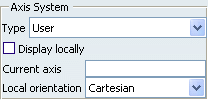
- User to use an axis system you created
(for example in the Part Design workbench or the
Generative Shape Design workbench).
- Local to use a axis system that is
locally defined relative to a finite element.

If you
selected User:
- Select the axis system in the specification tree.
The name of the selected axis is displayed in the
Current axis box.
- Select the type of coordinate system you want to
use: Cartesian, Cylindrical or
Spherical.
See
Coordinate System.
To display the
selected axis system locally on the geometry, select the Display locally
check box.
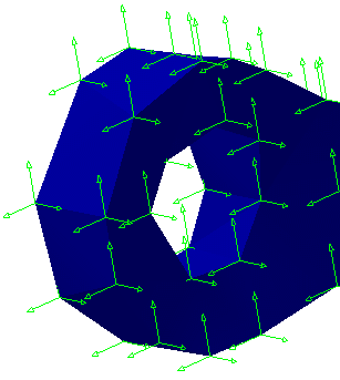
- Display locally option deactivated with
a Global axis system:

- Display locally option activated with a
Global axis system
:


Modify the Axis System in an Image Context
You can modify the axis system used in the image edition and when you export data to a file.
To modify the axis system in the context of the image edition and the
export data to file capabilities:
Click
 .
.
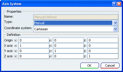
The Axis System dialog box appears.
In the Type list, select one of the
following:
- Global to use the default main axis
system.
- User to use an axis system you created
(for example in the Part Design workbench or the
Generative Shape Design workbench).
- Manual to use an axis that you define by
specifying the origin and the X, Y and Z axes.
- Local to use a axis system that is
locally defined relative to a finite element.
If you
selected User, select the axis system in the
specification tree.
If you
selected Manual, enter the coordinates of the origin and
the coordinates of two axes.

In the Coordinate system list, select the
type of coordinate system you want to use: Cartesian,
Cylindrical or Spherical. See Coordinate System.
Click OK.


 .
.