Adding a Protective Covering | |||||||||
|
| ||||||||
In the Electrical Part Design workbench, select Insert > Protective Covering
 .
.The Instantiate Protective Covering dialog box appears:
In the specification tree or the geometry area, select a segment.
The protective covering is placed over the segment.
In Standard mode, you can reposition both ends of the protective covering.
Note: The start and end of the protective covering are positioned with respect to a reference point. To change this point, double-click the appropriate label and select a new point.
Tips: - To cover all branch segments, select a first segment, press Shift and select the last segment in the branch.
- To place a protective covering over an existing covering, select the existing covering in the specification tree or geometry area.
To trim the protective covering, do one of the following:
- Drag the Start or End label along the center curve. As you trim, the distance between the selected end of the protective covering and the corresponding reference point is updated.
- Double-click the Start or End label and, in the dialog box that opens, enter a value in the Distance box then click Apply. The selected end of the protective covering is moved the specified distance from the reference point.
- Double-click the distance label and, in the dialog box that opens, enter a value then click Apply. The distance between the selected end of the protective covering and the corresponding reference point is adjusted as specified.
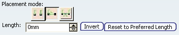
Switch to the Length placement mode.
In the geometry area, the length of the protective covering is now indicated and one end (End) is highlighted in red. This end is fixed and cannot be moved. Right-click an end to change its status.
Length mode lets you specify a length for the protective covering and allows you to reposition one end.
Note: In Length mode, you can select a segment end, protective covering end, support entry or exit point to to locate the start of the covering.
Move the Start label by 50mm.
To do so:
- Drag the Start label along the center curve.
- Double-click the distance label and, in the dialog box that opens, add 50mm to the value in the Distance box then click Apply.
Note: The covering length remains the same.
To specify a length, do one of the following:
-
In the Instantiate Protective Covering dialog box, type the value or use the arrows to change the value in the Length box.
- In the geometry area, double-click the length label and, in the dialog box that opens, enter a new value.
Note: Click Invert to flip the protective covering.
For information about the Creating a Protective Covering from Scratch, see Creating a Protective Covering from Scratch.
-