Creating a Protective Covering from Scratch | ||||||
|
| |||||
In the Electrical Part Design workbench, select Insert > Protective Covering
 .
.
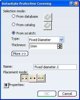
Select the From scratch selection mode.
The dialog box appears as:
Optional: Click More>> and set other parameters.
Parameters are displayed depending on the selected covering type.
Notes:
- The bend radius is not taken into account when computing the segment using the standard algorithm. It is only used with the FLEX algorithm. However, this parameter lets you create knowledge rules.
- The flexibility slider sets the stiffness used when computing segments using the Flex Algorithm.
- The line type defines how coverings will be represented
on drawings.
- To set your own drawing line type, select a value in the Line type list.
- To represent the covering in double line (projection) mode, select the No line type check box.
- You can set a default line type in Tools > Options... > Equipment > Electrical Discipline > Electrical Assembly Design > Electrical Geometry Management > Protective Covering Instantiation area.
Set the placement mode to Center.
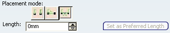
The Center mode lets you center the protective covering on a point. The length of the covering on either side of this point is the same.For information about other placement modes, see Adding a Protective Covering.
In the specification tree or the geometry area, select a segment.
The protective covering is centered on the point (segment end, protective covering end, support entry or exit point) nearest your selection. This point highlighted in blue when you move the pointer over a segment is the reference point.
Note: The From scratch mode can be de-activated by clearing the Authorize from Scratch mode check box (Tools > Options... > Equipment > Electrical Discipline > Electrical Assembly Design > Electrical Geometry Management tab).