Integrating Generative View Style (GVS)
The Generative View Style (GVS) gives you access to dress-up capabilities
in the Drafting workbench when working on Electrical Harness Flattening
documents. It allows the user to store the customizing options of drawing
(Single / Double Line, 2D Detail, 3D Projection, etc.).
2D details showing pre-defined Support Section Views are automatically
generated as defined in GVS.
To customize a Drawing View, you can use
General Parameters but it is highly recommended to use the Generative View Style.
Make sure the Drafting > View options are set as described in
View, in the Settings Customization Guide.
When the Generative
View Style is not activated (Tools > Options > Drafting > Administration),
select the following options in the Drawing tab of the
General Parameters dialog box:
The aim of
these settings, stored in the Flattening Parameters, is to customize
the Drawing.
Open the
Tools > Options... menu, then the Mechanical Design
> Drafting > View tab. In the Geometry generation / Dress-up
frame, select the following options:
-
Project
3D wireframe
-
Project
3D points
Click
OK to validate. Note that the
Generative View Style only works on Electrical Harness Flattening data,
that is to say after extraction from the 3D data. GVS allows to generate the drawing with:
- 2D Detail for Ends of Protective Coverings
The same 2D detail is used for
both ends of the protective covering. This is why, when defining the detail,
the administrator must respect detail symmetry about the x-axis.
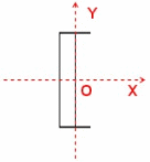
The center of the detail is
placed on the end point of the protective covering and the OX axis of the
detail follows the tangency of the curve at the previous point. When generating the drawing,
2D details are sized according the layer of protective covering to which
they are applied. You can take the 2D detail into account,
the user must set the attribute, External reference, to the name
of the catalog detail. By default, if the External reference value is set on a protection reference, then instantiating a protection feature from this protection reference should set the same value on the External reference of the instantiated protection feature. You can also do as follows:
- Right-click the instantiated
protective covering and select Properties from the contextual menu.
- Click More...
in the Properties dialog box that opens.
- Select the Electrical
tab and enter the name of the 2D detail in the drawing catalog in
the External Reference field.
- Click OK
when done.
To better visualize the various
overlapping layers of protective covering on your drawings, you can use
different Line Types and 2D Details. For more information, please refer
to Distinguishing Overlapping Protective Coverings. For more information, see About Customizing a Drawing View.
- 2D Details for Support Section
Views
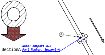
By default, one 2D detail per
support section will be generated. Details are positioned on the drawing
on a grid. Details of support sections are oriented according to the orientation
of the support in the 3D view. Supports are identified by a
letter and corresponding details are identified using the same identifier
plus a prefix, if desired.
- 2D Details for Support Section
Views
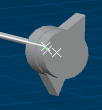
In this example, the arrow on the right side
is a 2D Detail is superposed on the 3D projection of the support.
The symbols used will either be:
- images from the catalog if you filed the External_Reference field in your protective covering properties with a Knowledge parameter
- or a symbol named after the support part number
The Automatic Generation leads to the creation
of:
For more information, see About Customizing a Drawing View. In this example, the arrow on the right side
is a 2D Detail is superposed on the 3D projection of the support.
The Automatic Generation leads to the creation
of:
For more information, see About Customizing a Drawing View.
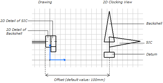
- 2D Clocking View
A 2D Clocking View displays the relative position between a Backshell and a SIC (the SIC being connected to this Backshell). The orientation of the Backshell with respect to the SIC is taken into account in the drawing generation / update. Thus, the drawing contains three 2D Details: Backshell, SIC and Datum. To generate 2D Clocking View in the drawing, you need to:
- Open a flatten geometry.
- Set the GVS parameters: activate the GVS and complete the 2D Clocking View options under the Device node.
- Generate a Front View.
- Run the Automatic Generation and Update Dress-Up to respectively generate and update the drawing according to the GVS.
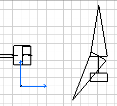
Here is an example:
To measure the relative angle between the Backshell and the SIC, the system uses the local axis of the 3D Part. The angle value will be correct only if constraints (defined at the Backshell Connection Point) are up to date. 2D Details of the Backshell and the SIC should exist in catalog with a part number following this naming rule: SIC / Backshell + _Clocking, in
geometry data. 2D Detail for Datum should also be present in catalog, with the same name as mentioned in the GVS. 2D Detail representing Clocking View is created in the direction of the segment connected to the Backshell. Datum and Backshell 2D Details are the reference (no rotation is applied to them) and the SIC 2D Detail is rotated according to the relative angle applied in geometry data.
Note:
The orientation between the Backshell and the SIC can be computed even if the orientation constraint is not defined at the Backshell Connection Point. The angle computation is based on the transformation between local axis system of the Backshell and the 3D part (SIC).
Open the
Tools > Standards... menu. The Standard Definition
dialog box opens. - Select
generativeparameters in the Category list.
- Select
GVS_sample_1.xml in the File list.
The electrical
components are displayed with their representation. For example,
the graphic representation is:
In the Standard
Definition dialog box, now select the DefaultGenerativeStyle.xml
in the File list. The electrical components are displayed with their
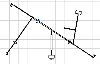
representation. If you select
this generative view style to generate a Front View drawing
 ,
the drawing looks like this: ,
the drawing looks like this:

Creating Line Type Standards
You can create your own line type standard for protective coverings that
gives a different aspect to these components in your drawing and lets you
better visualize the various overlapping coverings. This functionality is
only available when generating drawings using Generative View Style parameters.
For each basic line type, you must define more than one bi-dimensional
line type, increasing its size as you go in order to obtain one line type
per layer of protective covering.
When generating your drawing, the system maps the appropriate line type
to each layer of protective covering using a simple formula.
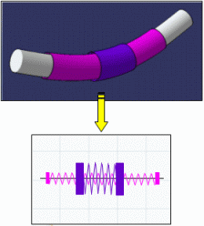
The above illustration also shows 2D details applied to the ends of protective
coverings that likewise vary in size according to the covering layer. For
more information, see Integrating Generative View Style.
Before you begin:
- you must run a CATIA session in administrator mode (see CATIA
Installation and Administration User's Guide).
- Have specified the location of customized standards by setting the
CATCollectionStandard variable. To learn more about the CATCollectionStandard
variable, see
About Standards.
Select the Tools > Standards... menu item.
The Standard Definition dialog box pops up. In the Category list box, select drafting.
And in the File list box, select ANSI.xml.
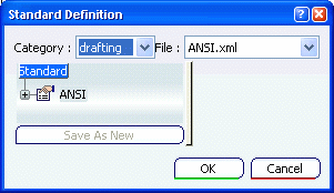
The Save As New command is now available.
Select LineTypes in the left-hand list:
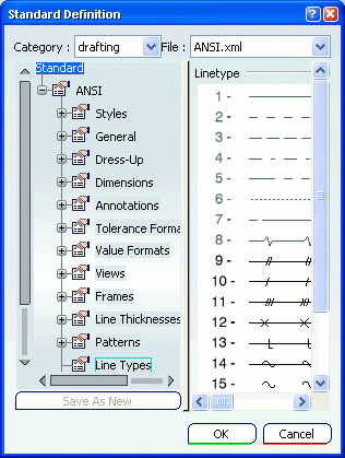
Click Save As New and save the document with
another name in the folder you specified by the CATCollectionStandard
variable.
This way you can customize more than one line type standard,
that for example, will allow you to produce drawings having
different line types for different customers.
Then double-click a line in the list and modify its
aspect.
Define more than one bi-dimensional line type per basic line type you
want to create, increasing its size as you go so that you will obtain
one linetype per layer of protective covering.
Your document is updated. When creating protective coverings,
line types offered in the Line type list are taken from the
Tools > Options > General > Display > Linetype tab.
To map line types in the standard you have just created to
those in the Tools > Options dialog box,
you must update the list in the Linetype tab.
To update line types in the Linetype tab,
select the Tools > Options menu item. The Options
dialog box displays:
Select the General > Display >
Linetype tab.
Double-click one of the line types you created in the
steps above. The Linetype editor dialog box opens.
Select the corresponding line type number previously
created and click OK to validate. The list in the Options
dialog box is updated.
Repeat for other line types.
Click OK to validate the changes in the Options
dialog box. You can now use this line type standard for your drawings.
For more information, see:
Interactive Drafting User's Guide - User's Tasks - Administration
Tasks - Administering Standards and Generative View Styles
Interactive Drafting User's Guide - User's
Tasks - Administration Tasks
- Setting Standard Parameters and Styles -
Setting Standard Parameters -
Linetype Definition.

Using the Product Resource Management
|
![]()

![]()


