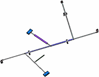
Open the flattened
document.
Switch to the
Drafting workbench and open a new drawing document.
Click Front View
 and select the top-face of the rectangular connector as Plane.
The drawing document updates according to this choice.
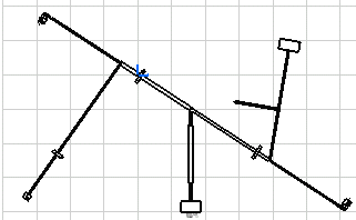
Click Automatic
Generation
 .
The drawing is updated according to the generative view style previously
defined: .
The drawing is updated according to the generative view style previously
defined:
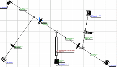
Automatic
Generation options are stored within the GVS. The following
example shows the definition of the segment template, with a predefined
type of text template:
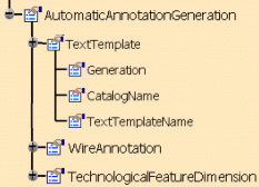
Text Templates are generated on:
-
segments
-
protective
coverings
-
supports
-
connectors
(single insert connectors, ground studs, internal splices, external
splices, terminal strips and terminal blocks)
-
Backshells
Wire
Annotations are generated on:
- Segments
- connectors
(single insert connectors, ground studs, internal splices, external
splices, terminal strips and terminal blocks)
Support
Sections are generated on:
-
a ditto
for each support section, with
-
appropriate
labels on the support itself and on the section for easy identification.
2D Clocking View is generated for:
- Backshell and SIC relative orientation
Text
Templates, Conductor Annotations , Support Sections
and 2D Clocking View are defined in the GVS. They are placed at a default location but can be
moved for better legibility or presentation. To do so: - Drag the
annotation you want to move:
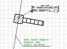
- Release
the mouse button when you are satisfied with the new position.
If you modify
the original 3D document for example to: - Change
a segment diameter
- Change
a connector / device position
- Add or
remove a branch, etc.
You will need
to update the drawing. To do so: - First
click Synchronize
 to
reflect the modifications of the geometry on the flattened document.
For more information, please refer to
About Synchronization. to
reflect the modifications of the geometry on the flattened document.
For more information, please refer to
About Synchronization.
- Then
click Update Current Sheet
 to reflect the modifications of the geometry on the drawing.
- Finally
click Update Dress-up
 to:
to:
|