Select (or press Ctrl+P) .
In the Print dialog box, the type of printer you choose determines the default settings:

Select a printer in
the drop-down list next to Printer Name.
On Windows, you can select the printers provided by Dassault
Systemes
which are managed with dedicated plot configuration
files. Dassault Systemes
Printer Manager is part of the V6 Windows environment,
combined with the native Microsoft printer manager.
Optional: To print to a
file, select the Print to file check box
then
enter a file name or click File Name....
Click Properties... to access the printer
properties then click OK
when finished.
If the driver is provided by Dassault Systemes,
see Adding a Printer.
Define the page orientation.
- Orientation settings differ from one printer
to another.
- The current format and page size set by clicking Page setup...
is displayed as a reminder.
Select the fitting option.
Position the image either by:
- Dragging it to its new position.
- Entering its position of the bottom and left corners of
the image (with respect to the paper margins).
- Using the
Origin and Center buttons.
Click Page Setup....
In the
Page Setup dialog box, define the paper format and margins:
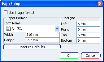
For a standard paper format, Width and
Height indicate the paper format compliant with the
ISO 216 standard and the Width/Height ratio
defined in this format is constant (i.e. 1/ 2).
2).
- If you set a new
format, the image of the paper format and the image to be printed
are resized accordingly.
- If the selected format is incompatible
with the printer currently selected, a warning message is displayed
but this
does not prevent you from setting the paper format.
Select the
image orientation.
Select the Print Area.
Note that the Whole Document mode potentially modifies
the viewpoint to reframe all the geometry (position and zoom
factor). Therefore, the result might look different from the user's
view. The result also depends on the workbench you are using.
Click Options....
In the Color tab, set
the color type for the image to be printed:
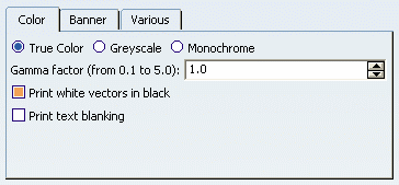
Optional: Click the Banner tab.
If needed, you can delete the $USER, $DATE and $TIME
variables which, by default, print the user name, and the
current date and time in the banner at the bottom of the
printed output to replace them with the text of your choice.
You can also use the following variables: $EYE (provides the eye origin coordinates for 3D documents
only), $NAME (refers to the printed document), $HOST, $SCALE, $DAY, $MONTH, and $YEAR.
Note:
The application does not control the display of the banner text, whatever
the value you enter in the Banner text height box.
Therefore, it is recommended to preview the banner to make sure that the text is entirely displayed.
Click the Various tab.
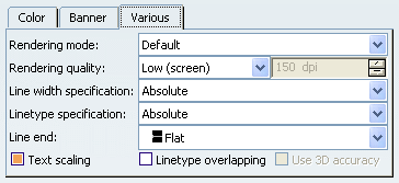
Set the Rendering
mode to be used for printing.
- The Dynamic Hidden Line Removal mode available in this tab and the
Dynamic hidden line removal mode available in the View Mode
Customization dialog box generate similar results but use
different technologies. Therefore, even though the results look
similar, they might not be absolutely equivalent.
- When the Shading with Triangles mode is selected, you can print UVR files.
Set the Rendering quality
factor which determines the quality of the printed output.
Set the Line width specification and the
Linetype
specification.
Use the Line end
list to choose how line ends are drawn.
This option is especially useful for drawing representations
and does not impact the print preview. See also
Raster Format.
Optional: Use the check
boxes at the bottom of the tab to define the 3D accuracy, the text
scaling and the linetype overlapping.
The Use 3D accuracy check box is activated only when
working in Hidden Line Removal rendering mode.
Optional: Select the Tiling
option then click Define....
In the Options dialog box, specify how the image should be cut to be printed on several pages.
Click OK to close the Tiling dialog box.
In the Print dialog box, click OK.
Your parameters are validated and the object is printed.
