More About Customizing Print Settings | ||
| ||
Printer Selection Through a Filter
You can search for a printer using a filter.
- Click Printer Name:
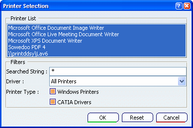
The list of defined printers is displayed in the Printer List area. By default, all printers are highlighted.
- In the Filters area, enter the string to be searched for in the Searched String box. You can use the character * as a wildcard.
- Select the driver on which you want to perform the search (e.g. CGM, HPGL, etc.) in the Driver list.
- Indicate a printer type by selecting the appropriate option: Windows Printers or CATIA Drivers.
- Press Enter to run the search: the list is updated and
displays only the printers corresponding to the search criteria.
If you are not satisfied with the search, click Reset to go back to the default options.
- When satisfied, click OK to validate and close the
Printer Selection dialog box.
The list of printers is filtered according to your search criteria.
![]()
Print Preview
The print preview and the print result might differ depending on the document format and the line thickness used in the document.
HPGL, HP-GL2 and PostScript
The preview of HPGL, HP-GL2 and PostScript documents generated by V6 may look different from one release to another whereas the printed result will be identical.
If you need to compare two files generated on two different releases, we recommend that you use a printed output and not a preview image. Previewing such files is relevant only for checking the file content.
Line thickness
Line thickness is not processed identically when visualizing and when printing a document. For each line thickness defined in mm in the standards of a drawing document or in the default thickness parameters, a corresponding thickness in pixels is associated.
- When displaying the document on screen, the width used is the one defined in pixels. When printing the document on paper, the width used is the one in mm.
- When previewing the document, an alternate pixel thickness is used: one pixel every 0.3 mm. This alternate thickness is closer to the paper mm thickness than the usual pixel thickness used for display. For instance, if internal edges of a model are defined with a thickness of 0.16 mm and 1 pixel on screen, and external edges have a thickness of 0.2 mm and 2 pixels on screen, then the print preview uses one pixel for both the internal and external edges.
- Tessellation discrepancies may appear between the preview and the print result.
- Linetype and line thickness are displayed in pixels in the Print Preview window and thus, they are different from the print result which is in millimeters.
![]()
Rendering Modes
The printed output might differ according to the selected rendering mode and the object type.
Default
Two parameters are taken into account for the printed output: the rendering style and the object type.
The rendering style is the one defined in the View Mode Customization dialog box.
For instance, if a part is displayed in Wireframe, the Default rendering mode generates a vector image and for Drafting objects, a vector plot is performed).
Part Design, Assembly, or V4 objects
The rendering mode used to print Part Design, Assembly, or V4 objects depends on the selected print area.
When the print area is Display:
- If the window's rendering style is Shading, the print is performed in Rasterization mode (pixel).
- If the window's rendering style is Hidden Line Removal, the print is performed in Hidden Line Removal mode (vector).
- Otherwise, the print is performed in Shading with Triangles mode (vector).
2D Layout objects
The rendering mode used to print 2D Layout objects depends on the selected print area.
When the print area is Display:
- If the window's rendering style is Shading, the print is performed in Rasterization mode (pixel).
- If the window's rendering style is Hidden Line Removal, the print is performed in Hidden Line Removal mode (vector).
- Otherwise, the print is performed in Shading with Triangles mode (vector).
When the print area is Whole Document or
Selection:
- If Display all elements using Z-buffer depth is activated in , then the print is performed in Rasterization mode.
- If the window's rendering style is Shading, the print is performed in a mixed Rasterization and Wireframe mode: it superimposes a pixel image and a vector image. See 2D Layout for 3D Design User's Guide for more information.
- If the window's rendering style is Hidden Line Removal, the print is performed in Hidden Line Removal mode (vector).
- Otherwise, the print is performed in Shading with Triangles mode (vector).
Consequently, the image displayed on screen and the printed image are not necessarily exactly the same.
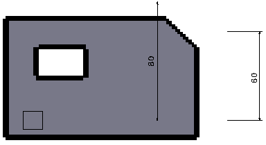
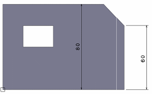
In case of the mixed Rasterization and Wireframe mode for a 2D Layout window, a pixel image and a vector image are superimposed. The fitting precision of both images depends on the requested rendering quality or dpi. The higher the dpi, the better the fitting.
Note that to allow a quick preview, the dpi used when previewing
the image is often lower than the requested dpi. The requested dpi
is used only when printing the document. This is illustrated by the
pictures below:
- Visualization:
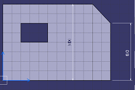
- Preview
. Approximate fitting due to a low dpi:
- Printing. Actual printing to an HPGL2 printer with a proper dpi:
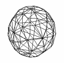
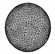
Shading with Triangles
The Shading with Triangles rendering mode enables you to print UVR (Ulead Cool 360 Viewer) files with a fine tessellation for edges, lines and faces, whatever their distance from the camera.
UVR files have a scene graph based on UV mapping. UV mapping is a 3D modeling process which wraps a 2D image (called a "texture map") onto a 3D object. "X", "Y" and "Z" are the coordinates of the original object in the 3D space and "U" and "V" are the coordinates of the resulting object.
| Shading with Triangles is not selected | Shading with Triangles is selected |
|---|---|
 |
 |
Rasterization
In Rasterization mode, an additional action might be needed on some operating systems and there is a specific behavior when using the Hidden Line Removal rendering style.
GdiPlus
For operating systems older than Windows XP (Windows NT, Windows 2000, etc.), GdiPlus.dll must be installed before using the Rasterization mode.
To do so, browse the following Internet site then follow the instructions:
http://www.microsoft.com/downloads/details.aspx?FamilyId=6A63AB9C-DF12-4D41-933C-BE590FEAA05A&displaylang=en
Hidden Line Removal
The Hidden Line Removal rendering style can be replaced by another rendering style for performance reasons.
If the visualization mode has been switched to Hidden Line Removal (using ) to improve performance, the generated image is computed by replacing the Hidden Line Removal rendering style by the Dynamic hidden line removal rendering style available in the View Mode Customization dialog box.
In that case, these two rendering styles give very similar results, the only difference is that Dynamic hidden line removal is a lot faster. To avoid this rendering style replacement and generate an image with the Hidden Line Removal rendering style, use the CATPrintRasterNoForcedHRD=1 variable.
![]()
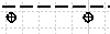
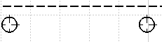
Linetype specification
Linetypes are visualized with a pattern in pixels and are printed with a pattern in millimeters.
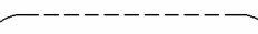
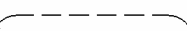
When you zoom the object onto which the linetype has been applied, the visualization algorithm applies the pattern as many times as there are zooms and therefore, the linetype always looks the same:
| Before zooming. Linetype 3 | After zooming. Linetype 3 |
|---|---|
 |
 |
But when you print the object, the pattern is applied according to the geometry's length. Therefore, if the geometry's length is lower than the pattern's size, the pattern is only partially applied.
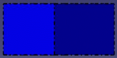
In Absolute mode, as the pattern size is preserved, the applied pattern count depends on the print scale. The pattern is applied with respect to the paper size.
In Scaled mode, as the pattern is scaled, the applied pattern count does not depend on the print parameters. The pattern is applied with respect to the model size.
For instance, a 200% print scale in Absolute mode means that the number of patterns applied is two times greater than the number of patterns applied in Scaled mode:
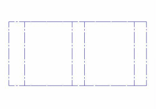
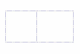
| Absolute mode. Linetype 3, zoom: 200% | Scaled mode. Linetype 3, zoom: 200% |
|---|---|
 |
 |
Overlapping
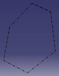
When printing 3D objects, a linetype overlapping can occur for 3D edges which overlap in 2D.
To solve this, you need to print the document using the polyhedral Hidden Line Removal rendering mode (HLR rendering mode + the Use 3D accuracy option activated).
Below is an example of a print preview in Wireframe rendering mode and in HLR rendering mode with the Use 3D accuracy option selected:
| Front View | Top View |
|---|---|
 |
 |
| Wireframe rendering mode: linetype overlapping for some edges | HLR rendering mode with Use 3D accuracy: no more linetype overlapping |
|---|---|
 |
 |