Placing End Cuts

You can place end cuts of the stiffener to maintain the connectivity. Set of standard end cuts are defined in endcut table which is set in Project Resource Management.


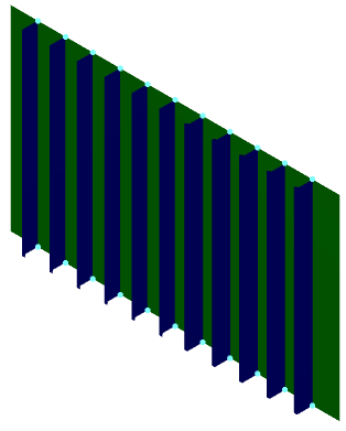
Before you begin: Create a bulkhead with number of stiffeners. In this scenario number of vertical stiffeners are placed on the transversal bulkhead.
Related Topics
End Cut Dialog Box
Endcut Table
Editing and Deleting End Cuts
Connection Set
  1. Click EndCut in the Connection toolbar.

    The End Cut dialog box is displayed.

  2. Select a bulkhead.

    All the stiffeners on the bulkhead are selected in the Profile box.
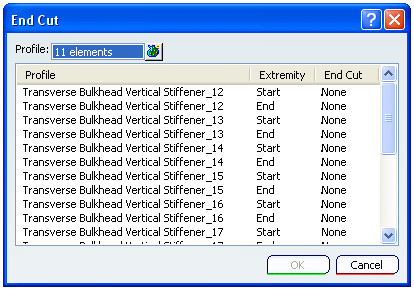
    Note: To select

    • A Stiffener out of many attached to the plate, you need to select it in 3D session.
    • All the Stiffeners attached to a Plate simply select a plate. All attached stiffeners will get selected.

    Tip:

    You can select the extremities in one of the following ways:

    In the End Cut dialog box:

    • Press Ctrl and select each extremity manually.
    • Sort and then select a bunch of extremities by pressing Shift key.

    In the 3D session:

    • Click to select each extremity manually. It gets highlighted in the End Cut dialog box.
    • Click close to one extremity. All the extremities in its close proximity get selected. These appear highlighted in the End Cut dialog box.

  3. Select the extremities to place the end cut.

  4. Right-click the stiffener displayed in the Profile area and select Define End Cut > More ...

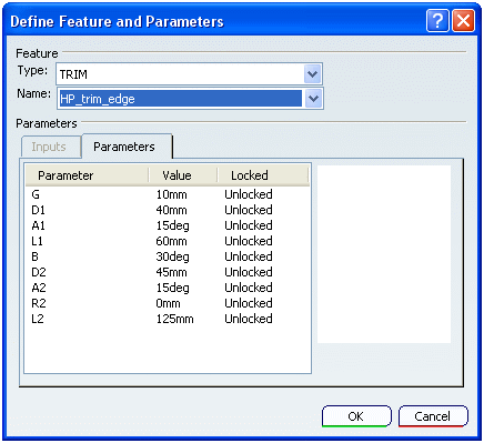
  5. The Define Feature and Parameters dialog box appears.

    1. Select the Type from the list.
    2. Select the Name from the list.

    The Parameters for the end cut are displayed in Parameters area.
  6. Click OK to place the end cuts.


Important:
  • End cuts are indicated by circular dots in the graphics area.
  • While creating a stiffener if you specify the limits then the default end cut selected is Short Point.