Modifying 2D Texture Properties

You can edit the material texture properties.


Before you begin: Make sure you select a product with a material already applied to it.

For more information on how to create materials refer to Creating Materials in the Material Editor User's Guide.

Related Topics
More about Modifying 2D Texture Properties
Defining Reflection Settings
Modifying Material Lighting Properties
  1. Double-click a material domain in the specification tree.

  2. Click the Rendering tab in the Domain Edition dialog box:


  3. In the Type box, select the type of texture you want to apply.

  4. In the Image Name box, navigate to locate the desired image, and click OK to map it onto the preview element as the texture.

    For more information about image formats refer to About Image Formats

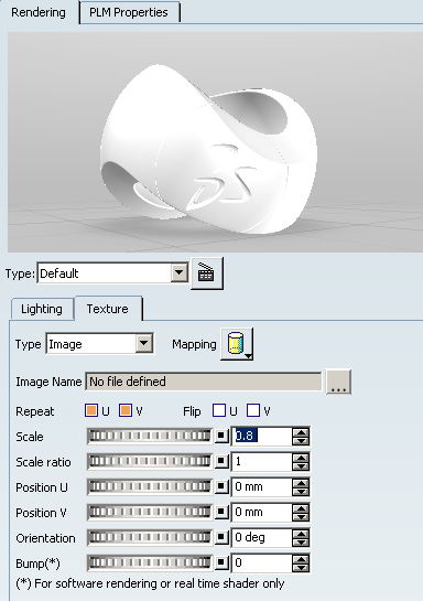
  5. Click Change Mapping type to choose from the different mapping types :


    Planar
    Spherical
    Cylindrical
    Cubical
    Auto Adaptive
    Manual Adaptive

    The Automatic Adaptive Mapping automatically creates a planar mapping on each object face.

    During the automatic adaptive mapping operation, the surface may show a discontinuity in texture, as displayed below:
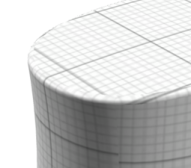
    Automatic Adaptive Mapping

    It can be made continuous by manual mapping, provided the curvature of the surface is not too high, as shown below:


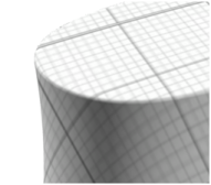
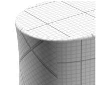
    Manual Adaptive Mapping (Mini) Manual Adaptive Mapping (Maxi)

    Manual Adaptive Mapping gathers together faces which have close normal vectors. For each group of faces, a unique planar mapping is applied. The precision value defined using the slider modifies the tolerance used during the grouping process: the lower the precision, the more faces with greatly different normal vectors are gathered together. This manual mapping enables textures to cross slightly sharpen edges, thus providing a higher visual quality.

    For more information on the mapping types refer to About 3D Textures in the Realistic Rendering User's Guide.

    Tip: You can also manipulate the object (i.e. zooming in/out, etc.) directly in the geometry area while displaying the Domain Edition dialog box either by double-clicking the material in the specification tree or by right-clicking the material then selecting xxx object > Definition.

  6. If necessary, change the Material size to adjust the scale of the material relative to the part.

  7. Define the image scale, its position and its orientation:

    U and V correspond to parameters of the local parametric surface.

    • Repeat U, V
    • Flip U V
    • Scale ratio
    • Position U, V
    • Orientation

  8. Use the Flip U and Flip V check boxes to invert the material texture along U and V axes.

  9. You can click Links U and V scales to resize U and V proportionally. This is especially useful for square shapes like floor material for instance. When this option is on, the Scale V box is grayed and the icon changes to .

  10. The Bump slider lets you create a bump mapping effect when applying 2D textures. For more information on the bump mapping refer to the Bump Mapping Effect in the More about Modifying Material Texture Properties section.

  11. Click OK to validate the material texture definition. The material icon reflects the material as defined. Note that there is no specific order for defining parameters.

  12. Position the material interactively using the robot as explained in Materials.