Click Hole
 if you want to create a hole in Part Design, or click Hole
 to create a hole in Functional Modeling Part.
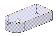
Select the face on which you wish to create the hole.

In the Hole Definition dialog box that displays,
define the hole shape and enter the parameters of your choice.
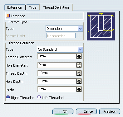
Click the Thread Definition tab.
Select Threaded to access the thread definition
options.

In the Type box, you can choose among two
default
thread
types . You can also:
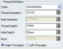
Set your own file containing personal standards in the
Type box. In our example, set 'StandardGaz'.

If necessary, edit the thread depth then the hole depth
if you need to modify the value you had previously set in the Extension
tab. This value must not exceed the thread diameter value.
Select Left-Threaded.
Click OK to confirm your operation and close
the Hole Definition dialog box.
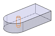
The application displays the hole in the geometry area but
not the thread. Note also that an icon specific to this feature
is displayed in the specification tree. The icon below is the
one used if you have created a hole in the Part Design workbench.

