Creating Holes | ||||||||
|
| |||||||
Click Hole
 to create a hole in Part Design or Hole
 to create a hole in Functional Modeling Part.
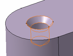
Select the circular edge and upper face as shown.
The application now defines one distance constraint to position the hole to be created. The hole will be concentric to the circular edge.
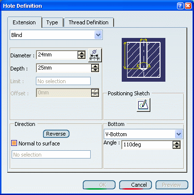
The Hole Definition dialog box appears and the application previews the hole to be created. The Sketcher grid is displayed to help you create the hole.
Tip: Click  to open the Sketcher. You can then constrain the point
defining the hole position. Once you have quit the Sketcher,
the Hole Definition dialog box reappears
to let you define the hole feature. For more information,
see Locating Holes.
to open the Sketcher. You can then constrain the point
defining the hole position. Once you have quit the Sketcher,
the Hole Definition dialog box reappears
to let you define the hole feature. For more information,
see Locating Holes.Whatever hole you choose, you need to specify the bottom limit you want.
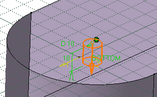
There is a variety of limits. By default, the application previews a blind hole whose diameter is 10mm and depth 10mm. Keep the Blind option.
Set the Bottom option to V-Bottom to create a pointed hole and enter 110 in the Angle box to define the bottom shape.
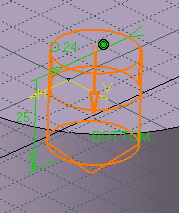
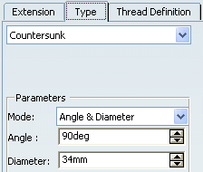
You are going to create a countersunk hole. To create such a hole you need to choose two parameters among the following options:
- Depth & Angle
- Depth & Diameter
- Angle & Diameter
Set the Angle & Diameter parameters in the Mode box.
You can notice that the image assists you in defining the desired hole.

Click OK.
The hole is created. The specification tree indicates this creation. You can notice that the sketch used to create the hole also appears under the hole's name. This sketch consists of the point at the center of the hole.
If working in the Functional Modeling Part workbench, Hole.X is added to the specification tree in the Solid Functional Set.X node. By default, as a protected feature, holes are in No Show mode. To see the red protected area you have just created, set the Show mode.