Creating or Editing a Tool Holder | ||||||
|
| |||||
Create a Conical Tool Holder
You can create a conical tool holder.
From any product:
- Alternatively, open an existing Machining Process or PPR context .
 By default,
the
Activities Process Tree opens
automatically.
By default,
the
Activities Process Tree opens
automatically.
- Alternatively, open an existing Machining Process or PPR context .
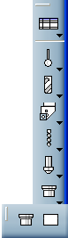
If the Tool Builder toolbar is not visible, select
The Tool Builder toolbar is displayed. The icons used to create a tool holder are found in the Holder sub-toolbar:
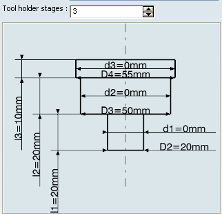
A conical tool holder is defined by diameters and lengths.
The Tool Holder Definition dialog box is displayed.
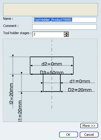
Define the number of Tool holder stages (between 2 and 5).
- For two stages, specify the two tool
holder diameters (D2 and D3) and two cone diameters
(d1 and d2). Suitable values for the cone diameters allow
the stages to be tapered.
- For five stages, specify the five tool
holder diameters (D2 to D6) and five cone diameters
(d1 to d5). Suitable values for the cone diameters allow
the stages to be tapered.
The icon representing the tool holder is updated accordingly:
- For two stages, specify the two tool
holder diameters (D2 and D3) and two cone diameters
(d1 and d2). Suitable values for the cone diameters allow
the stages to be tapered.
Double-click any value in the icon representing the geometry of the tool holder to edit it in the dialog box that appears.
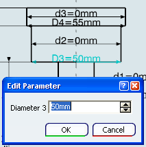
The representation icon is updated with the new values.
An alternative is to click More>>
A Geometry is displayed.
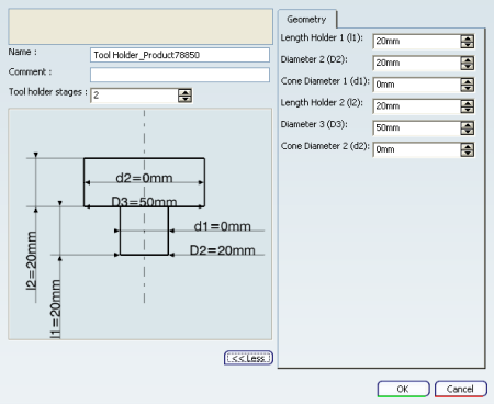
Click OK to create the tool holder and exit the dialog box.
It is added to the Machining Cell, for example as Tool Holder_xxx.
 .
.
![]()
Create a Prismatic Tool Holder
You can create a prismatic tool holder.
From any product:
- Alternatively, open an existing Machining Process or PPR context .
By default,
the
Activities Process Tree opens
automatically.
- Alternatively, open an existing Machining Process or PPR context .
If the Tool Builder toolbar is not visible, select
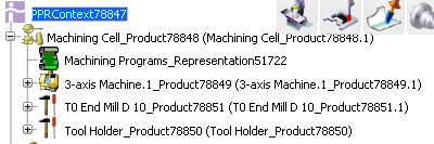
The Tool Builder toolbar is displayed. The icons used to create a tool holder are found in the Holder sub-toolbar:
The Tool Holder Definition dialog box is displayed.
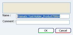
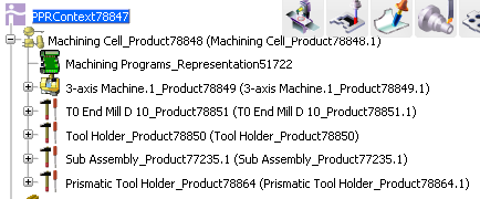
It contains only a Name and a Comment.Click OK to create the tool holder and exit the dialog box.
It is added to the Machining Cell, for example as Prismatic Holder_xxx.
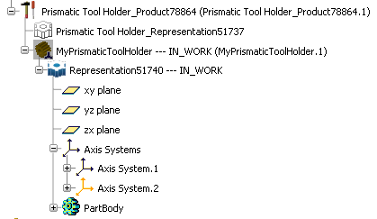
Now you must associate a 3D Part to Prismatic Holder_xxx.
This 3D Part contains the geometric description and two axis for mounting purpose.
- Make the 3D Part invisible and revert to Machine Programming.
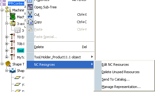
- Right-click Prismatic Holder_xxx and select in the contextual menu.
The Manage Representation dialog box appears.
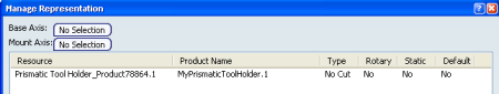
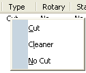
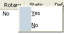
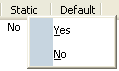
- Type, Rotary and Static status are proposed with a default value. Use their contextual menus to change them if necessary.
The prismatic tool holder is now defined.
- Make the 3D Part invisible and revert to Machine Programming.
 .
.