Right-click the top view in the specification tree or
in the sheet and select Activate back-clipping plane.
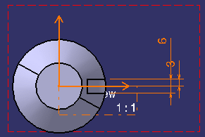
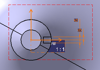
The top view now contains a plane that clips the background
that is behind it.
Note:
All 2D elements of the layout view itself
are still visible, independently of the plane's size and position. This
lets you work in the layout view as usual, adding geometry, annotations
and dress-up for example.
You can now define the back-clipping plane's position
in 3D space according to your design's needs. This position is defined
by the distance between the layout view plane and the back-clipping
plane.
To do so, right-click the front view and select
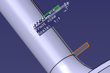
Edit back-clipping plane. A 3D viewer is displayed. The back-clipping
plane is visualized using an orange frame and the layout view plane
using a green frame.

You can either:
- Specify the plane's position relatively to the layout
view plane by entering a value in the Depth field.
- Drag the back-clipping plane.
Click Apply to view your modifications.
When you are satisfied with the back-clipping plane's
position, click Close to validate and exit the dialog box.
The background of the top view is back-clipped as specified.

To deactivate the back-clipping plane, right-click the
top view and select Deactivate back-clipping plane.
The top view's whole background is displayed again as
the back-clipping plane is de-activated.
