About 2D Layout For 3D Design Views | ||||
|
| |||
Design views
Design views are views in which you design and whose content can be visualized and output in 3D context.
The following sub-topics are discussed:
Primary Views
Primary views are design views which have no parent view and set the distribution of their children views, grand-children views, and so on.
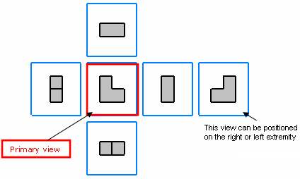
The primary view type can be any projection view type (Front, Left, Right, Top, Bottom or Rear) and it is determined by the standard file embedded in the 3D shape representation. There is no associative property between the primary view type and the standard. Therefore, the type of existing primary views will not be changed when updating the embedded standard with a standard which has another primary view type.
The name of a primary view corresponds to its view type. For example, a primary view of the left type is named "Left view". The specification tree does not distinguish primary views from other views. (To know which view is the primary one, you may use knowledge capabilities).
Layout sheets may have several primary views of different types.
A view box is associated to each new primary view. Thus, design views created from primary views are created according to their associated view boxes and not from the standard's definition, which keeps the position of linked views in 3D space coherent. Note that it is not possible to edit the view box from an existing primary view.
Miscellaneous Remarks About Primary Views
You can select the following reference elements for view creation:
- 3D Plane: The direction of the primary view created from 3D planes is along the normal of the 3D plane. The view lies on a plane parallel to the selection.
- Sketch
- Face
- FTA view
- Inverse and Rotate of plane
- Axis system: The XY plane of the axis system is considered as support in case of selection of a right-handed or left-handed axis system. The Z-axis gives the view box its orientation for a right-handed axis system, otherwise the orientation is the opposite of the Z-axis i.e. the direction of the primary view created will be along Z-axis. The center of the view box coincides with the axis system origin, whatever the 3D axis position may be.
| Important: If no selection is performed while creating a primary view, then the view type and its orientation on the view box is changed when using the arrows of the robot. In this case, you can see that the view type and orientation is changing when clicking the arrows. |
The following remarks apply to the 2D position of primary views:
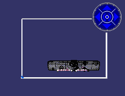
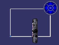
- The 2D position of each newly created primary view is computed such that the projection of the center of the 3D shape or assembly coincides with the center of the 2D window.
- After the primary view is created, you may modify its position on the
sheet. Further, if you use the robot to rotate the view, then the 2D view
position is stabilized such that the center of the 3D shape or assembly is
still projected to the same 2D position.
Original position:
New position with the center of the 3D shape projected to the same 2D position:
The following remarks apply to the direction of primary views:
- The direction of primary views created from 3D selection (except the
3D planes and axis system) depends on the selection plane and the bounding
sphere center. From the selection plane, the new primary view is created
on the closest side from the selection. In this case you can see that the
blue plane is created on the other side which is closer.
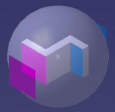
- The direction of primary view created from 3D planes is along the normal of the 3D plane. In the case of an axis system, the direction of primary view created is along the Z-axis of the axis systems.
Sections
In the 2D Layout for 3D Design workbench, when activating the Cutting Plane icon, representations of section cuts and section views are identical (for the background of a section cut is still visible).
However, it is useful to differentiate these two view types from their 3D creation, because once projected in the Generative Drafting workbench, section cuts and section views are represented correctly.
To distinguish a section cut from a section view in a layout, you can customize the visualization. Activate the back-clipping plane, then edit a low depth. The background of the section cut will be less visible.
![]()
Isometric views
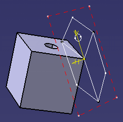
Isometric views differ from projection views to a certain extent. In 3D space, isometric views would be located at the corners of the view box. However, they are not visualized outside the 2D Layout for 3D Design workbench.
Note: Isometric views are visualized only in the 2D Layout for 3D Design workbench (not in a 3D window).
The example here shows the positioning of an isometric view in 3D space:
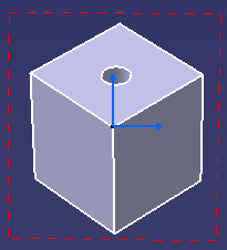
The purpose of isometric views is to check by transparency the validity of the 3D design, that is to compare the result of a 3D shape creation (from one or several design views) with the expected original design:
Note: You cannot use the robot to customize the creation of isometric views.


