Creating a Pathway | ||||||||||
|
| |||||||||
Open the Create Pathway command by doing one of the following:
- Click the arrow on the west quadrant of the Compass to open the toolbar and then in the toolbar click Create Pathway
 .
. - Click .
A balloon appears:

A pathway set is added to the RFLP tree under the active system or sub-system. It contains one pathway and one segment. The pathway set name is automatically generated by the system (however you can modify the name; right-click the name in the RFLP tree and select ).
- Click the arrow on the west quadrant of the Compass to open the toolbar and then in the toolbar click Create Pathway
Optional: To set options for the pathway, in the balloon click
 .
.The Pathway Options dialog box appears.
Define your options and then click Close.
Optional: To set offset options, in the balloon click
 .
.The Define offset mode and offset value dialog box appears.
Define your options and then click Close.
If necessary, you can reopen this dialog box at any time while you are creating the pathway.
In the balloon, select a point positioning mode:
 Basic Creation Mode: Move the pointer in the 3D area; it will detect Pathway Branch Points,
Pathway Connection Points (PCP), 3D points, and points and surfaces on 3D shapes. Hold down Ctrl to create passing points offset from a shape. To reverse the offset direction, also hold down Shift.
Basic Creation Mode: Move the pointer in the 3D area; it will detect Pathway Branch Points,
Pathway Connection Points (PCP), 3D points, and points and surfaces on 3D shapes. Hold down Ctrl to create passing points offset from a shape. To reverse the offset direction, also hold down Shift. Key-in XYZ Coordinates: Enter your own x, y and z coordinates for a point.
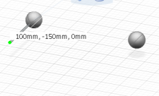
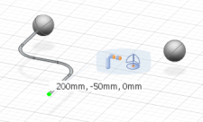
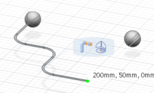
 Route along robot base plane: Click in the 3D area to place a point on the robot base plane. Reposition the robot to change the base plane if necessary.
 Create New Point using Robot: Drag the robot; when you release, a point is created.
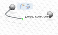
Use the point positioning mode selected (or a combination of any of the modes) to create the pathway, going from point to point.
Tip: In order to connect to a shape at each end of the pathway, use Basic Creation Mode or Create New Point using Robot for the start and end points. You can use these or any of the other point positioning modes for the intermediate points.When you have finished your pathway, in the balloon click Exit Command
 .
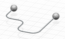
.The pathway is created.
Important: If a shape at the end of a pathway is subsequently moved (using the Robot), the pathway will adjust automatically to the new position of the shape during an update.
![]()
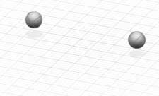
Example
The following example shows the stages of creating a pathway between two basic shape spheres using Route along robot base plane :
 |
 |
 |
 |
 |
 |