About Pathway Point Placement Modes | |||||
|
| ||||
The Placement Modes balloon lets you select the placement mode:
| Choose this mode... | To place a point... |
|---|---|
 |
On a shape, near a shape, on a pathway connection point or on other pathways. |
 |
Using coordinates with reference to an origin. |
 |
With reference to the robot base plane. |
 |
Anywhere in the 3D view by manipulating the Robot. |
Basic Creation Mode
This section describes the Basic Creation Mode for positioning of a point on a pathway.
Using this mode, you can:
- Connect pathways to basic and detailed shapes.
- Connect pathways to pathway connection points.
- Connect pathways to other pathways.
- Create intermediate passing points.
The green dot indicates the position at which the point will be created. Visual clues tell you what kind of point you are creating:
| This visual clue... | Indicates you are creating... |
|---|---|
 |
A pathway connection point on a basic shape or on a detailed shape. |
 |
A connection with an existing pathway connection point (PCP). |
 |
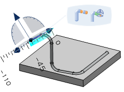
A passing point. The square represents the reference plane in which the point is created. The line to the green point indicates the offset distance set in the Define offset mode and offset value dialog box. Hold down Ctrl to create these points. To reverse the offset direction, also hold down Shift. |
 |
A pathway connection point on another pathway. |
![]()
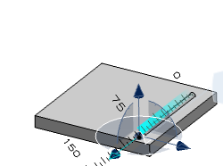
XYZ Coordinates
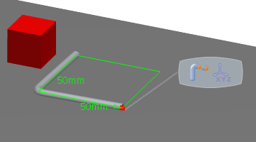
This section describes the options in the Define coordinates dialog box which you can use to position a point on a pathway.
Choose one of the following reference points as the origin of the XYZ coordinates:
- To use the origin of a shape, select the shape.
- To use the default origin, click
 .
. - To use the robot location, click Robot location.
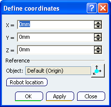
Tip: You can adjust this reference point at any time during positioning of a pathway point or a series of points. Enter values for X, Y and Z or use the arrows to change the values.
In the example shown, X and Y are both set to 50mm. The green arrows show these as vectors from the origin.
To position the pathway point, do one of the following:
- To position the point and immediately close the dialog box, click OK.
- To position the point and then move on to the next point, click Apply. The pathway is immediately extended to the XYZ coordinates. Change the values of X, Y and Z and then click Apply again. The pathway is immediately extended to the new XYZ coordinates. Continue to add points and extend the pathway in this way. When you are happy with the series of points, click Close; the dialog box closes.
![]()
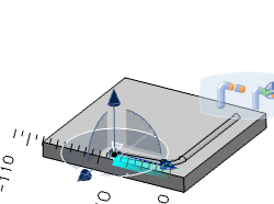
Robot Base Plane
This section describes the Robot Base Plane mode for positioning of a point on a pathway.
Drop the robot onto a shape. The plane of the robot base becomes the new reference plane and all your pathway points are now confined to this reference plane.
Each time you click in the 3D area a pathway point is created at that position in the reference plane.
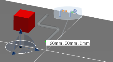
At any time you can drag the robot to a different location. You can then continue creating pathway points using the new plane of the robot base as the reference plane.
![]()
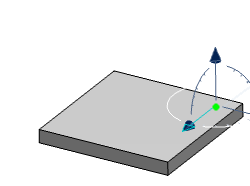
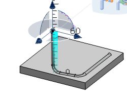
The Robot
This section describes the Robot mode for positioning of a point on a pathway.
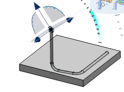
Select your starting point on a shape. The robot is positioned at the starting point. Drag the robot to a new position. When you release the robot, a new point is formed. Continue to drag and release until your pathway is complete.
At any time you can drop the robot onto a different shape or rotate the robot. The robot base plane is adjusted to the new position and you can then continue routing by dragging and releasing.
 |
 |
 |
 |
 |
 |
 |