Creating a Sweep | ||||||
|
| |||||
Click any icon requiring a shape definition. For example, launch the Shellable Feature capability
 ,
then click Sweep
,
then click Sweep
 in the Shellable Feature dialog box that appears.
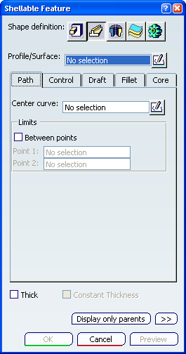
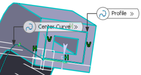
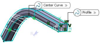
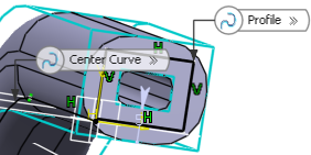
Select the profile you want to sweep.
Important: All the Shape features have a Profile/Surface as part of the Prism geometry definition. - If you launch the command with no profile previously
defined, click Sketcher
 sketch the profile you need.
 - You can also select:
- Any face originated by functional features of any Functional Body. In this case, the face needs to be the original untrimmed (unmerged) of the feature.
- Any topological (trimmed) face of any Part Design body that is not the Part Body containing the active Functional Body.
- If you launch the command with no profile previously
defined, click Sketcher
Click the Center curve box and select the sketch you need or click the Sketcher
icon to sketch the center curve you need.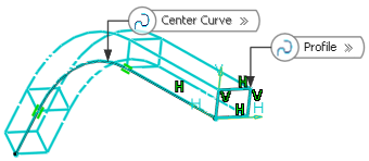
Important: - Selecting the Between points option defines the sweep between two points along the path (other than the endpoints). You merely need to select the points of your choice to define Point 1 and Point 2.
- The Profile/Surface needs to be between the two points along the path. When if the Profile/Surface is outside of the two points, the feature will be created from the spot of the sketch on the path keeping the same length of the distance between the two points.
Select the Thick check box. This option enables you to add material to both sides of the profile.
- If you enter 5mm in the Inside Thickness
field and click Preview. Thickness is evenly distributed to both sides of the profile.
If you select Outside Thickness in the Reference list and click Preview. The thickness you defined for Inside Thickness is added to the inside of the profile.
If you enter 3mm in the Outside Thickness box. The application previews how the thickness is added to the outside of the profile.
- If you enter 5mm in the Inside Thickness
field and click Preview. Thickness is evenly distributed to both sides of the profile.
Select the Lateral radius check box if you want to fillet lateral edges. Then, set the radius value of your choice.
Select the First radius check box if you wish to fillet top edges. Then, set the radius value of your choice.
Select the Second radius check box if you want to fillet the opposite bottom edges. Then, set the radius value of your choice.
- You can select the Draft fillets check box from the Fillet tab. For more information, see More About Draft Fillets.
Select the Constant Thickness check box. This option allows you to apply lateral fillets to the feature with a constant wall thickness.
- If you select Neutral Fiber in the Reference list, lateral fillet radius is applied at neutral fiber.
- If you select Outside Thickness in the Reference list, lateral fillet radius is applied at outside thickness face.
If you select Inside Thickness in the Reference list, lateral fillet radius is applied at Inside thickness face.
Note: For more information, see More About Thick Option.
Important: The Core capability enables you to define a core body (offset) for a shellable feature. - If you select Neutral Fiber in the Reference list, lateral fillet radius is applied at neutral fiber.