About Prisms | ||||
|
| |||
Limits Tab
The Limits tab available in various feature dialog boxes lets you define lengths in various ways.
All the prism shapes of the functional features have two boundaries at the opposite sides of the extrusion direction. For shape features and rib functional feature they are called First length and Second length. For some functional features (cutout and pocket) there are Floor and Opening on each side.
By default, the application specifies the length of your prism.
There are six ways of defining lengths. Depending on the feature you are defining, the length option selections vary. These options are:
- Length: You just enter the value you need.
- Through All: The feature extends the protected volume itself along the prism extrusion direction outside the boundaries of the functional body.
- To Shell: The feature extends to trim the volumes at an offset of the shell
(external, added, protected, internal, core, cutout, pocket, boss,
rib, reinforcement, remove feature and intersect feature).
Note: To Shell is available when a shellable feature is present in the solid functional set.
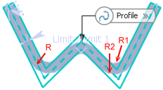
- To Plane/Surface: The plane or surface you select trims
the prism. In alternative to the selection of a plane/surface, you
can select a sketch, a sketch output or a sketch output profile as
profile. In this case a surface is automatically extruded along the normal to the
sketch plane.
It is also possible to trim the prism at an offset distance from the plane or surface. If existing planes or surfaces do not meet your needs, you can use any of these creation contextual commands available from the empty box:
- Create Plane: Creates a plane by using one of the method described in Generative Shape Design User's Guide: Creating Wireframe Geometry: Creating Planes.
- XY Plane: The XY plane of the current coordinate system origin (0,0,0) becomes the trimming element.
- YZ Plane: The YZ plane of the current coordinate system origin (0,0,0) becomes the trimming element.
- ZX Plane: The ZX plane of the current coordinate system origin (0,0,0) becomes the trimming element.
- Create Join: Joins surfaces or curves. See Generative Shape Design User's Guide: Performing Operations on Shape Geometry: Joining Surfaces or Curves
- Create Extract: Generates separate elements from non-connex sub-elements. See Generative Shape Design User's Guide: Performing Operations on Shape Geometry: Extracting Geometry: Extracting Elements.
- To Parting Element: The parting element specified in the draft properties is used to set this limit. For this, you need to define Draft behavior option in the Draft tab.
Note: You cannot select this option to define the First length as well as the Second length at the same time.
- To Neutral Element: The neutral element specified in the draft properties is used to set this limit.
Note: You cannot select this option to define the First length as well as the Second length at the same time.
![]()
Draft Tab
This section describes the various options available in the Draft tab.
Draft behavior
The Draft behavior box lets you chose how you want to generate drafts:
- None: There is no draft.
- Intrinsic to feature: You can perform a draft operation
by defining the following:
- Angle: You can enter the angle value.
- a Neutral element: You need to define a neutral element.
- Draft Properties: You can perform a draft operation by defining the following parameters with
the faces to be drafted:
- A neutral element
- Faces to draft
Note: You need to define draft properties prior to the creation of the prism to choose Draft Properties in the pull down menu.
Neutral element
The following options let you define a neutral element:
Profile plane: It is the default neutral element (defines a neutral curve on which the drafted face will lie).
First limit: Automatically selects a face.
Second limit: Automatically selects an alternate face.
- Plane/Surface: If this option is chosen, the Selection box is active. You need to select the plane or surface of interest. You can select a sketch. When the sketch is selected, a Generative Shape Design surface will be automatically built internally.
- Use parting element: This option is available when Draft properties is selected. The neutral element is equivalent to the selected Draft Properties Parting element.
Faces to draft
The Faces to draft option controls which faces are drafted.
There are three options:
- All lateral faces
- Selected by pull direction: Automatically selects the faces to draft to be those that are parallel to the pull direction vector.
- Select profile curves: This method allows you to specify
which faces to draft by picking curves of the boundary profile.
I.e.: the defining profile curve for the face. You need to select
Curves.
There are two options available:
- First limit
- Second limit
Parting Element
When the Profile Plane or Plane/Surface options are chosen to define the neutral element, then the Parting=Neutral option is active by default. Moreover, when the Parting=Neutral option is active, Draft both sides becomes active too. If the Draft both sides option is on, the draft will be symmetrical on the parting element.
- Parting=Neutral: If this check box is selected, the plane or surface you selected as the neutral element is also used as the parting element.
- Draft both sides: If this check box is selected, the draft operation applies to both opposite directions from the parting element.
- Draft fillets: If this check box is selected, the fillets are applied before the draft is created. Sometime small edges that do not lie on the parting surface might be created. With this option, the fillets will become the variable radius fillets instead of the constant fillets and it prevents from generating the extra edges.
With the Draft fillets check box cleared With the Draft fillets check box selected Important: This option is also available in the Fillet tab. It operates simultaneously in the both Draft and Fillet tabs.
![]()
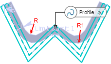
Fillet Tab
This section describes the various options available in the Fillet tab.
The Fillet tab options are described in Creating a Prism Here are simple examples of the Fillet profile ends option.
 |
 |
| Prism with lateral radius on, Fillet profile end off | Prism with lateral radius on, Fillet profile end on |
 |
 |
| Prism with First radius on, Fillet profile end off | Prism with First radius and Fillet profile end on |
 |
 |
| Prism with Lateral, First, and Second radius on, Fillet profile end off | Prism with Lateral, First, Second radius, Fillet profile end on |
![]()
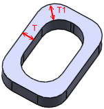
Thick Option
This option is available for closed as well as open sketches.
Constant Thickness
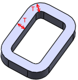
The Constant Thickness option is available when you select the Lateral radius check box in the Fillet tab. It allows you to apply lateral fillets to the feature with a constant wall thickness (T).
 |
 |
| With Constant Thickness check box cleared | With Constant Thickness check box selected |
The thick feature with constant wall thickness is maintained in the imported feature.
Closed Sketches
The following options are available in the Reference list when you select the Lateral radius check box in the Fillet tab:
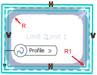
- Outside Thickness: Lateral fillet radius (R) is applied at outside the thickness face.
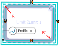
- Neutral Fiber: Lateral fillet radius (R) is applied at neutral fiber.

- Inside Thickness: Lateral fillet radius (R) is applied at inside the thickness face.
Open Sketches
The following options are available in the Reference list when you select the Lateral radius check box in the Fillet tab:
- Thickness1: Lateral fillet radius (R) is applied at one side of the thickness face.
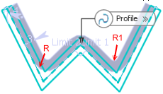
- Neutral Fiber: Lateral fillet radius (R) is applied at neutral fiber.
- Thickness2: Lateral fillet radius (R) is applied at other side of the thickness face.