Creating a Cutout | ||||||
|
| |||||
Click Cutout
 in the Basic Features toolbar.
 The Cutout dialog box appears.
Select the closed profile on which you are going to base the cutout.
Tip: If no profile is defined, clicking Sketcher  enables you to sketch the profile you need.
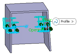
The prism is the default shape. Just click Sweep
 if you want to change. For the purposes of our scenario, keep the default
option. Set the parameters and options as follows to define the shape
you want.
if you want to change. For the purposes of our scenario, keep the default
option. Set the parameters and options as follows to define the shape
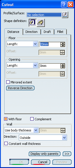
you want.- In the Distance tab, enter 17mm to define
Floor: Length.
Important: Instead of using the Length option, you can set the Through All option, which sets the value of the cutout length as zero. This extends the cutout infinitely from the profile plane in the specified direction. Because the cutout is a protected volume, the infinite volume is also protected. 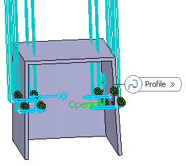
Preview of the Through All option defined for the Floor
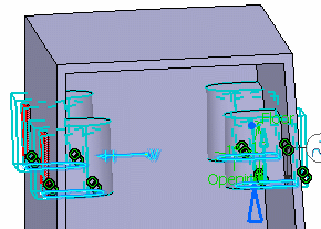
Opening: Length=0mm
Here again, instead of using the Length option, you can set the Through All option, which sets the value of the cutout depth as zero.
-
In the Direction tab:
Select the Normal to profile check box.
-
In the Draft tab:
Angle=1deg -
In the Fillet tab:
Clear all fillet options.
- In the Distance tab, enter 17mm to define
Floor: Length.
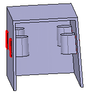
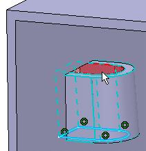
Click Preview to get an idea of what the cutout looks like. As a protected area, it is displayed in red:
Clear the With floor check box to see the difference. As indicated by the cursor, the cutout has no floor.
Click OK to confirm and create the cutout. Cutout.X is added to the specification tree in the Solid Functional Set.x node.