Creating a Prism | |||||||
|
| ||||||
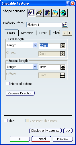
Launch any capability requiring a shape definition. For example, click Shellable Feature
 in the Basic Features toolbar.
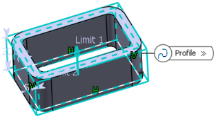
The Prism
 is the default shape proposed by the application.
Select a sketch or surface to define the prism.
In our scenario, select a rectangle. When done, the selected element is displayed in the Profile/Surface box of the Shellable Feature dialog box.
You can select an existing sketch, a sketch output, a sketch output profile profile or surface.
Important: - If you launch the command with no profile previously
defined, click Sketcher
 to sketch the profile you need.
 - You can also select:
- Any face originated by functional features of any Solid Functional Set. In this case, the face needs to be the original untrimmed (unmerged) of the feature.
- Any topological (trimmed) face of any Part Design body that is not the Part Body containing the active Solid Functional Set.
- If you launch the command with no profile previously
defined, click Sketcher
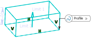
Enter the value of your choice in the First length box to define the feature length from the sketch plane. If you prefer, you can drag the LIM1 manipulator in the geometry area.
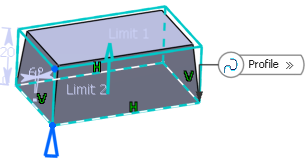
Important: You can also enter a value in the Second length box to define the feature length in the opposite direction. Set the Intrinsic to feature option, the profile plane as the neutral element and then enter the value of your choice to define the draft angle.
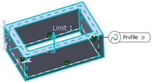
Select the Thick check box. This option enables you to add material to both sides of the profile.
- If you enter 5mm in the Inside Thickness
field and click Preview. Thickness is evenly distributed to both sides of the profile.
If you select Outside Thickness in the Reference list and click Preview. The thickness you defined for Inside Thickness is added to the inside of the profile.
If you enter 3mm in the Outside Thickness box. The application previews how the thickness is added to the outside of the profile.
- If you enter 5mm in the Inside Thickness
field and click Preview. Thickness is evenly distributed to both sides of the profile.
Select the Constant Thickness check box. This option allows you to apply lateral fillets to the feature with a constant wall thickness.
- If you select Neutral Fiber in the Reference list, lateral fillet radius is applied at neutral fiber.
If you select Outside Thickness in the Reference list, lateral fillet radius is applied at outside thickness face.
If you select Inside Thickness in the Reference list, lateral fillet radius is applied at Inside thickness face.
Note: For more information, see More About Thick Option.
Important: The Core capability enables you to define a core body (offset) for a shellable feature. - If you select Neutral Fiber in the Reference list, lateral fillet radius is applied at neutral fiber.