Optional: In the Name
box of the Face Face Connection Property dialog box, modify the name of the connection
property. In the Type
list, select one of the following: - Contact to prevent bodies from penetrating
each other at a common interface.
- Slider to fasten bodies together at their
common interface in the normal direction while allowing them
to slide relative to each other in the tangential direction.
If you selected Contact, click
 to define the contact parameters.
The Contact Definition dialog box appears. The
contact parameters are the clearance and the sliding effects.
The clearance is the minimum distance between the geometries of
the two sides of the connection.
- Choose one of the following clearances:
- Geometric to use a clearance that
is calculated automatically. The
geometric clearance is the current geometric
spacing between the surfaces.
- User-defined to enter a clearance value of your choice. A positive clearance
means that the surfaces can still come closer
until they are in contact, and is used to model
a known gap between the surfaces. A negative
clearance means that the surfaces are already
too close, and the system has to push them
apart; for instance, a negative clearance is
used to model a press-fitted clamp between the
surfaces.
- Choose one of the following behavior:
- Sliding to allow displacements along the tangential direction on
surface. To add friction behaviors, select the
Friction ratio check box, and enter a
ratio value in the Friction ratio
box.
- No sliding to constrain the
displacements along the tangential direction on
surface.
- Click Close.
In the Connected Geometries area, click
 to select the surfaces that are physically in contact.
The Connected Geometries dialog box appears. For more details about the supports you can select, see Supports for a Face Face Connection Property.
- In the Support 1 box, select the first set of
geometries to connect.
The application helps you to select the geometry by displaying the unnecessary geometries in low light mode and hiding the environment of the product that is not concerned by the assembly.
- In the Support 2 box, select the second set
of geometries to connect.
The application helps you to select the geometry by displaying the unnecessary geometries in low light mode.
- Click OK.
Click OK.
The face face connection property is created in the Connection Properties list. Face Face Connection Property.1
appears in the specification tree under the Simulation
set.
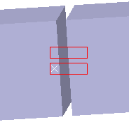
A contact connection
property is symbolized as shown below:

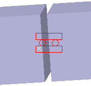
A slider connection property is symbolized as shown below:

|