Optional: In the Name
box of the Distant Connection Property dialog box, modify the name of the connection property. In the Type
list, select one of the following: - Rigid to give a rigid behavior to the
connection property.
- Smooth to give a smooth behavior to the
connection property.
In the Connected Geometries area, click
 to select the geometries that are physically in contact.
The Connected Geometries dialog box appears. For more details about the supports you can select, see Supports for a Distant Connection Property.
- In the Support 1 box, select the first set of
geometries to connect.
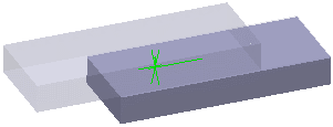
The application helps you to select the geometry by displaying the unnecessary geometries in low light mode and hiding the environment of the product that is not concerned by the assembly:

- Click the Support 2 box, and select the second set
of geometries to connect.
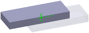
The application helps you to select the geometry by displaying the unnecessary geometries in low light mode:

- Click OK.
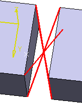
A symbol appears to represent the connection property. A rigid distant connection property
is symbolized as shown below:

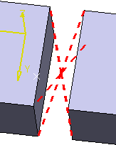
A smooth distant
connection property is symbolized as shown below:

Click OK.
The distant connection property is created in the Connection Properties list of the Engineering Connection dialog box. Distant Connection Property.1
appears in the specification tree under the Simulation
set.
|