In the specification tree, right-click an image and select Export
Values.
The Export Values dialog box appears.
In the Type
list, select the type of the export file (.xlsx, .xls or .txt).
Optional: The current axis
system of the (x,y,z) coordinates corresponding to the value
position (node, center of element...) is indicated in the Location
axis system box. To modify the axis system,
click
 .
.
To learn more about how to modify the axis system, see Modify the Axis System in an Image Context.
The axis system definition is exported in the
.txt, .xslx or .xls file (Location axis). The values of the axis system are exported. See Export of Axis System.The exported values depend on the axis system selected in
the Image Edition dialog box.
To indicate the
name of the mesh in the export file, select the Include mesh name check box.
Click OK.
The exported values are automatically displayed
in the appropriate application, depending on the format you chose. The Document / Document Customized dialog box also appears.
Optional: In the Name box, modify the name of the export document.
Click Finish.
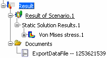
A Documents folder containing the export document is created under the Results category in the specification tree. For example:

If you propagate the simulation, the export documents you generated are automatically propagated in the database as documents attached to the simulation. To learn more about documents, see Simulations and Documents.
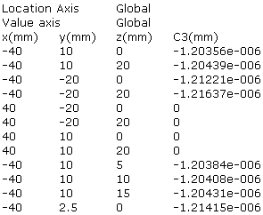
Example of exported values for a translational displacement vector image:
