Select Electrical Wire Reference  from the Electrical toolbar.
From the RFLP structure tree or from the 2D representation, select a parent component for your wire (Electrical System).
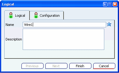
The Logical dialog box appears.

Type a name, Wire1 for example.
If need be, you can add a description in the Description field.
Click Finish to close the dialog box and create a wire reference.
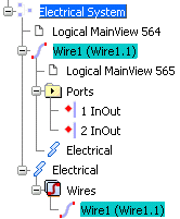
From the tree, under the parent component (Electrical System), note that:
- a Wire1 node is created.
- an Electrical node is created to store all electrical objeccts. In our example, it aggregates a Wires node containing the extended electrical component (Wire 1).

Right-click the wire, then select Properties from the contextual menu.
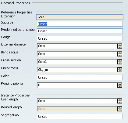
The Properties dialog box appears.
An Electrical tab has been created to display the electrical properties.
