Select Electrical Cable Extension  from the Electrical toolbar.
From the RFLP structure tree or from the 2D representation, select a logical component.
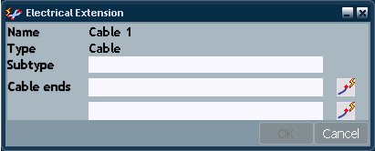
The Electrical Extension dialog box appears.

If needed, enter a description in the Subtype field.
Click OK to close the dialog box and add an cable extension to Cable1.
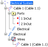
Under the system node (Electrical System), note that an Electrical node is created to store all electrical objects. In our example, it aggregates a Wires node containing the extended electrical net (Cable1).

Right-click the electrical component, then select Properties from the contextual menu.
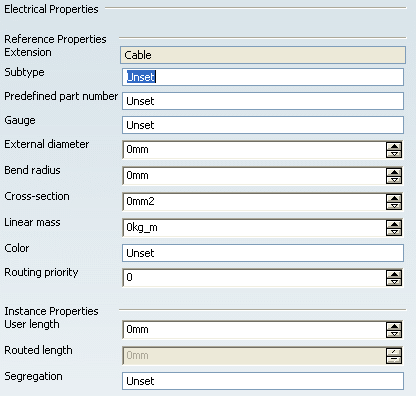
The Properties dialog box appears.
An Electrical tab has been created to display the electrical properties.
